Better Bus Modeling (How to remove Bus/Mux confusion)
Earlier this week, Guy and I were discussing the sometimes-strange behavior of mux and bus signals. Sometimes people find a Mux block in their model that appears to output a bus signal. In this post, I will explain the underlying cause of this behavior and give you a short Simulink history lesson.
Don’t let your eyes deceive you!
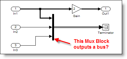
Most people have the correct mental model of the Mux block as a vector creator. When you see a Mux block, the expectation is it outputs a wide signal (a vector). Here is a very simple model that does not behave this way.

This is actually a misleading. Mux blocks are virtual, so they don’t actually do anything during the simulation. Virtual Bus signals are similar to Mux blocks. The Terminator is also virtual (it doesn’t update, compute outputs, etc.) When you consider those observations, all that is left are the ports and the Gain block.
Sometimes a Mux block can output a bus signal. Huh? But, I thought the Mux block created a vector!
The Mux Used to Create Bus Signals
A long time ago, in a much earlier version of Simulink, the Bus Selector was introduced to allow users to select signals by name from a bundle of signals. The Mux block created this “bundle” of signals. Simulink only supported vectors (no matrices), so there was very little difference between a virtual muxed signal and a virtual bus signal.
Soon after the introduction of the Bus Selector, developers added the Bus Creator to reduce confusion about the mixed meaning of Mux blocks. At the time, the Bus Creator still behaved much like a Mux block and actually shared code with the Mux block. For compatibility reasons, the Mux block had to continue supporting the creation of bus signals.
Over time, Simulink semantics changed and the difference between bus signals and vectors got more significant. In R14 Simulink (circa 2004), there were edge cases where the mixing of mux and bus caused problems. Simulink developers wanted to migrate to a clean bus modeling behavior, but it would break legacy models that depended on the Mux block to create bus signals. It was too dramatic a change to switch to the new and improved behavior without giving modelers a way to opt-in. How did they do it?
The Solution: Error Checking
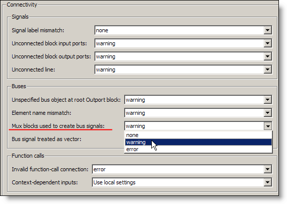
The Connectivity Diagnostic -> Mux blocks used to create bus signals was introduced to control this behavior. When a Mux block creates a bus, Simulink now handles it in one of three ways.

This diagnostic can be set to none, warning, or error.
none – This is the historical behavior of the Mux block, creating vector signals AND bus signals when needed. Full backward compatibility, plus the edge cases I talked about before.
warning – This is the historical behavior of the Mux block, plus a post compile check to find Mux blocks that might be used a bus creators. Simulink reports warnings it finds one.
error – This is the clean bus modeling behavior the developers implemented. If a Mux block is used to create a signal that is treated like a bus, an error stops the update diagram process.
Because this diagnostic asserts that it is an error to use a Mux block as a bus creator, Simulink assumes that only Bus Creators make bus signals. This assumption resolved the edge cases and made the clean bus modeling behavior possible. Because this is a diagnostic and the default is warning, legacy models still worked when people upgraded. Some issues were actually resolved by changing the diagnostic to error.
How to Fix the Warning/Errror
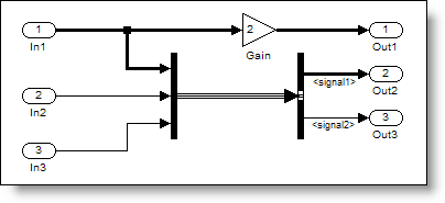
The warning and error messages provide some direction on how to resolve the problem. There are even commands you can call to help fix your model. This is an example of a model that produces a warning about mixing mux and bus.

Warning: The block diagram 'muxORbusWarning' improperly uses 1 Mux blocks as Bus Creators. This can lead to modeling errors (see the Mux block documentation for more information). To avoid such errors, replace the Mux blocks with Bus creator blocks and enable strict bus modeling (see slreplace_mux command). To enable strict bus modeling, set the 'Mux blocks used to create bus signals' option to 'error' in the Connectivity pane of the Diagnostics page in the Configuration Parameters Dialog.
Don't stop there!
For similar reasons you should also set Bus signal treated as vector to error.
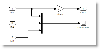
Fixing the original model
When the original model uses strict bus mode, the signal draws as a vector signal instead of a bus.

Now it’s your turn
The take away from this post is that you should set these diagnostics to error to get the BEST mux/bus behavior. Do you model in strict bus mode? Tell me about it and leave a comment here.


댓글
댓글을 남기려면 링크 를 클릭하여 MathWorks 계정에 로그인하거나 계정을 새로 만드십시오.