
What is a Composite Signal?
The answer is short and sweet. A composite signal is a mux or a bus signal. These can be thought of as a collection of other component signals. The subtleties of using bus signals and mux signals are a common source of modeling questions, and in 2006 The MathWorks published a new section of Simulink documentation to specifically discuss Composite Signals. In this post I will start to share my mental model of the mux and bus.
It started with mux
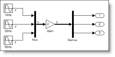
The basic concept for the Mux Block is the idea of bundling signals together. This bundle of signals can be routed through the model, and then operated upon as a collective unit. (Mux actually stands for multiplex.) Along with the Mux Block is the Demux Block, which breaks signals apart into their components to be operated on individually. Take a look at this example.
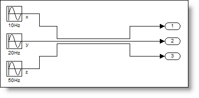
 The Mux is putting the three signals, (x,y,z) into a single line of width 3. The Demux Block is used to break apart the signals into their basic elements. The Mux and Demux do not change the signals, and are considered virtual. When the model is run, it is as if the blocks don’t exist, and only the connections from source to destination remain, like this:
 An important mental model to use for the mux is the idea of creating a vector. This means you can do things to the output signal that you would do with a vector. For example, multiply the vector by 2.
 These types of vector operations impose an important requirement that all signals passed into a Mux Block are the same data type. In my mental model of the mux, it only makes sense to lump signals together if they make sense as a vector. Usually the elements have the same units or they are useful as a group. The only specification you need for a Mux Block is the number of inputs.
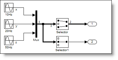
 Another benefit of using the mental model of a vector is that you can index with the selector block to pick off signals or rewire your connections.
 Later on came the bus
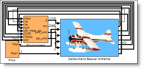
When I need to bundle together signals of different types or I can’t naturally express my diagram with a vector, I use a bus. Bus signals can really clean up your diagram. Bus Creators and Bus Selectors provide a graphically convenient way to manage signals and organize your model. In my mental model of the bus, I imagine a rainbow of wires bundled together with a tie-wrap. Without that tie-wrap holding it together I would quickly loose my ability to keep the signals organized. To demonstrate this, I want to look at an example model of the DeHaviland Beaver from the Aerospace Blockset:
Later on came the bus
When I need to bundle together signals of different types or I can’t naturally express my diagram with a vector, I use a bus. Bus signals can really clean up your diagram. Bus Creators and Bus Selectors provide a graphically convenient way to manage signals and organize your model. In my mental model of the bus, I imagine a rainbow of wires bundled together with a tie-wrap. Without that tie-wrap holding it together I would quickly loose my ability to keep the signals organized. To demonstrate this, I want to look at an example model of the DeHaviland Beaver from the Aerospace Blockset:
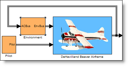 At the top level of the model, everything is nice and orderly because all the information calculated by each subsystem is bundled up into a bus. Each system packages all the relevant signals into a bus using a Bus Creator, and then passes the bus along to the systems that consume those signals.
 Can you imagine if the signals were not bused together? This is a relatively modest model, but it would be a mess!
 Most of the component systems in this model use bus signals to provide simplified interface. I have noticed that some people will place signals in the bus, just in case they might be needed in another system. Here is an example of a system whose interface is defined with bus signals.
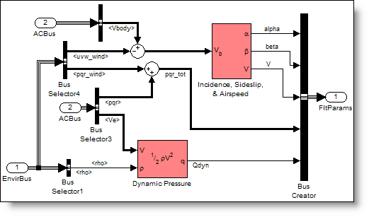
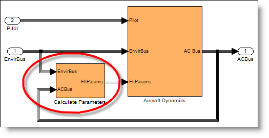 With a quick glance at this diagram you can determine that the flight parameters (FltParams) can be calculated from environmental signals (EnvirBus) and aircraft signals (ACBus). Inside the system you can see Bus Selectors used to pull specific elements from the bundle of signals. The computed flight parameters are combined with a Bus Creator to define the FltParams Bus.
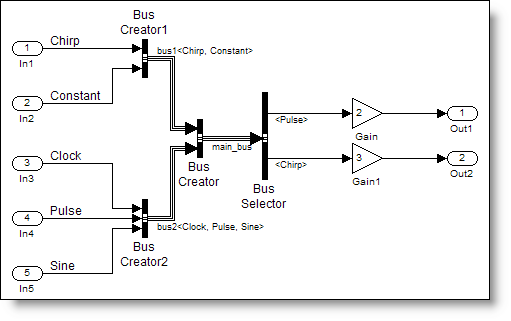
 Bus signals can represent hierarchy
Let’s look at the hierarchy found in the Environment Bus. This is a simple example of a bus being fed into another bus. The environmental signals for gravity (g), pressure (rho), and wind bus (Vwind) are passed into the Bus Creator. The wind bus is defined by the body velocities (uvw_wind) and body rates (pqr_wind).
Bus signals can represent hierarchy
Let’s look at the hierarchy found in the Environment Bus. This is a simple example of a bus being fed into another bus. The environmental signals for gravity (g), pressure (rho), and wind bus (Vwind) are passed into the Bus Creator. The wind bus is defined by the body velocities (uvw_wind) and body rates (pqr_wind).
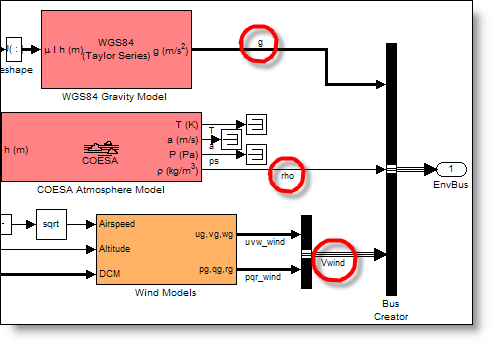 This leads to an organized collection of signals in the bus, as shown by the Bus Creator dialog.
 At its most basic level, you only need specify the number of inputs to your bus creator. The names of elements are derived from the signal names. Like the Mux Blocks, these bus creators have not changed the signals at all, so we can call them virtual.
It doesn’t end here
We are just starting to get into this topic. Next week we will talk about more advanced maneuvers with Mux and Demux Blocks, specifying interfaces with Bus Objects, and nonvirtual buses.
Now it’s your turn
How do you use bus and mux signals? What kinds of modeling questions about composite signals do you have? Care to share? Post a comment below. If you want to show off the complicated bus hierarchy from your model, e-mail me a picture of your bus and I’ll post it for you (image tags are stripped from comments).
At its most basic level, you only need specify the number of inputs to your bus creator. The names of elements are derived from the signal names. Like the Mux Blocks, these bus creators have not changed the signals at all, so we can call them virtual.
It doesn’t end here
We are just starting to get into this topic. Next week we will talk about more advanced maneuvers with Mux and Demux Blocks, specifying interfaces with Bus Objects, and nonvirtual buses.
Now it’s your turn
How do you use bus and mux signals? What kinds of modeling questions about composite signals do you have? Care to share? Post a comment below. If you want to show off the complicated bus hierarchy from your model, e-mail me a picture of your bus and I’ll post it for you (image tags are stripped from comments).
The Mux is putting the three signals, (x,y,z) into a single line of width 3. The Demux Block is used to break apart the signals into their basic elements. The Mux and Demux do not change the signals, and are considered virtual. When the model is run, it is as if the blocks don’t exist, and only the connections from source to destination remain, like this:
An important mental model to use for the mux is the idea of creating a vector. This means you can do things to the output signal that you would do with a vector. For example, multiply the vector by 2.
These types of vector operations impose an important requirement that all signals passed into a Mux Block are the same data type. In my mental model of the mux, it only makes sense to lump signals together if they make sense as a vector. Usually the elements have the same units or they are useful as a group. The only specification you need for a Mux Block is the number of inputs.
Another benefit of using the mental model of a vector is that you can index with the selector block to pick off signals or rewire your connections.
Later on came the bus
When I need to bundle together signals of different types or I can’t naturally express my diagram with a vector, I use a bus. Bus signals can really clean up your diagram. Bus Creators and Bus Selectors provide a graphically convenient way to manage signals and organize your model. In my mental model of the bus, I imagine a rainbow of wires bundled together with a tie-wrap. Without that tie-wrap holding it together I would quickly loose my ability to keep the signals organized. To demonstrate this, I want to look at an example model of the DeHaviland Beaver from the Aerospace Blockset:
At the top level of the model, everything is nice and orderly because all the information calculated by each subsystem is bundled up into a bus. Each system packages all the relevant signals into a bus using a Bus Creator, and then passes the bus along to the systems that consume those signals.
Can you imagine if the signals were not bused together? This is a relatively modest model, but it would be a mess!
Most of the component systems in this model use bus signals to provide simplified interface. I have noticed that some people will place signals in the bus, just in case they might be needed in another system. Here is an example of a system whose interface is defined with bus signals.
With a quick glance at this diagram you can determine that the flight parameters (FltParams) can be calculated from environmental signals (EnvirBus) and aircraft signals (ACBus). Inside the system you can see Bus Selectors used to pull specific elements from the bundle of signals. The computed flight parameters are combined with a Bus Creator to define the FltParams Bus.
Bus signals can represent hierarchy
Let’s look at the hierarchy found in the Environment Bus. This is a simple example of a bus being fed into another bus. The environmental signals for gravity (g), pressure (rho), and wind bus (Vwind) are passed into the Bus Creator. The wind bus is defined by the body velocities (uvw_wind) and body rates (pqr_wind).
This leads to an organized collection of signals in the bus, as shown by the Bus Creator dialog.
At its most basic level, you only need specify the number of inputs to your bus creator. The names of elements are derived from the signal names. Like the Mux Blocks, these bus creators have not changed the signals at all, so we can call them virtual.
It doesn’t end here
We are just starting to get into this topic. Next week we will talk about more advanced maneuvers with Mux and Demux Blocks, specifying interfaces with Bus Objects, and nonvirtual buses.
Now it’s your turn
How do you use bus and mux signals? What kinds of modeling questions about composite signals do you have? Care to share? Post a comment below. If you want to show off the complicated bus hierarchy from your model, e-mail me a picture of your bus and I’ll post it for you (image tags are stripped from comments). - Category:
- Signals


Comments
To leave a comment, please click here to sign in to your MathWorks Account or create a new one.