What’s New in Simulink in R2024b?
Looking at the Release Notes for Simulink in R2024b, what stands out the most to me is that we have improved a lot of already existing features.
Let's look at my favorites of those enhancements.
New Details panel for Quick Insert
When it was introduced many releases ago, the Quick Insert menu was a huge game changer. It completely changed the way to add blocks to a Simulink model. Instead of navigating the Library Browser and dragging the block into the model, Quick Insert allows you to just type the name of the block in the canvas and hit Enter.
In R2024b, we are adding a Details panel to this menu. It provides a description of the block and hyperlinks to documentation and examples:

Starting a Simulation in Debug mode
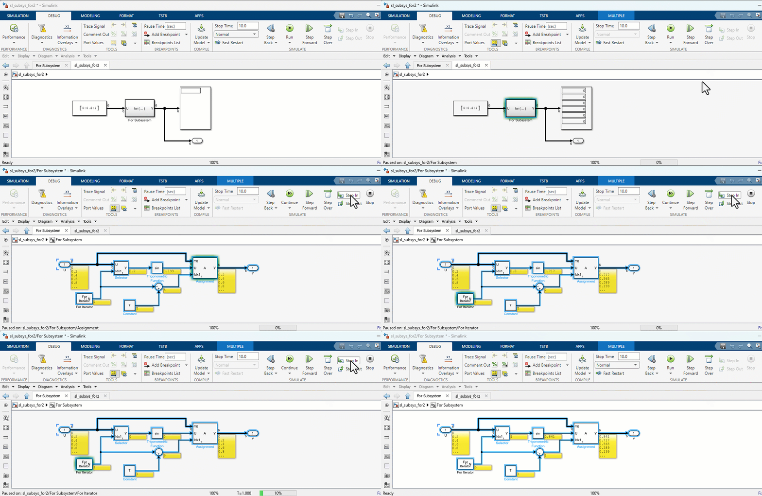
In R2023b, we introduced a new way to debug Simulink models, with the in-canvas debugger. Since then, the way to launch the block-by-block debugger was to add breakpoints on signal lines so the debugger would break as soon as the condition is met.
In R2024b, we decided to enable the Step Over button in the toolstrip when the simulation is stopped. Starting the simulation with this button will pause the simulation just before the first block executes, ready to debug from t=0. This is especially useful when the problem you are investigating is not obvious to capture with a change in value of a signal. Here is an example:

Connecting blocks across model hierarchy
The ability to programmatically create Simulink models is a major power of MATLAB + Simulink. For those using the add_block and add_line functions, you will love the new Simulink.connectBlocks.
Let's take this model:

I can connect the Gain block inside Subsystem A to the Bias block inside Subsystem B using this code:
blk1 = 'testConnect/A/Gain';
blk2 = 'testConnect/B/Bias';
Simulink.connectBlocks(blk1,blk2);
This will automatically add the Inport and Outport blocks required and connect all those blocks together.

In this case the result is one line of code instead of two calls to add_blocks and three calls to add_line. For more complex cases across deep hierarchies, the benefit is more significant. Look at the documentation for Simulink.connectBlocks to see all the possibilities.
Improved Bus handling in Model Reference Conversion Advisor
Let's say I have a simple model with a bus signal entering a Subsystem:

I can now convert it to a Referenced Model and the resulting model will look exactly like the original, and the bus element ports will include the entire bus definition, so no need for bus objects.

Customize Sample Time Colors
Since the beginning of time, sample time colors in Simulink have always been the same: D1 is red, D2 is green, D3 is blue, etc. In R2024b, we finally implemented the long-standing request of allowing users to customize sample time colors.
It's quite simple. Create a simulink.sampletimecolors.Palette object, define your colors in RGB or Hexadecimal color code and apply it:
h = simulink.sampletimecolors.Palette("myColors");
h.DiscreteSampleTimeColors = ["#aed6f1"; "#85c1e9";"#3498db";"#2874a6"];
simulink.sampletimecolors.applyPalette(h);
Here the resulting sample time legend for my "50 shades of blue" palette:

Adding Model blocks and Referenced Subsystems made easier
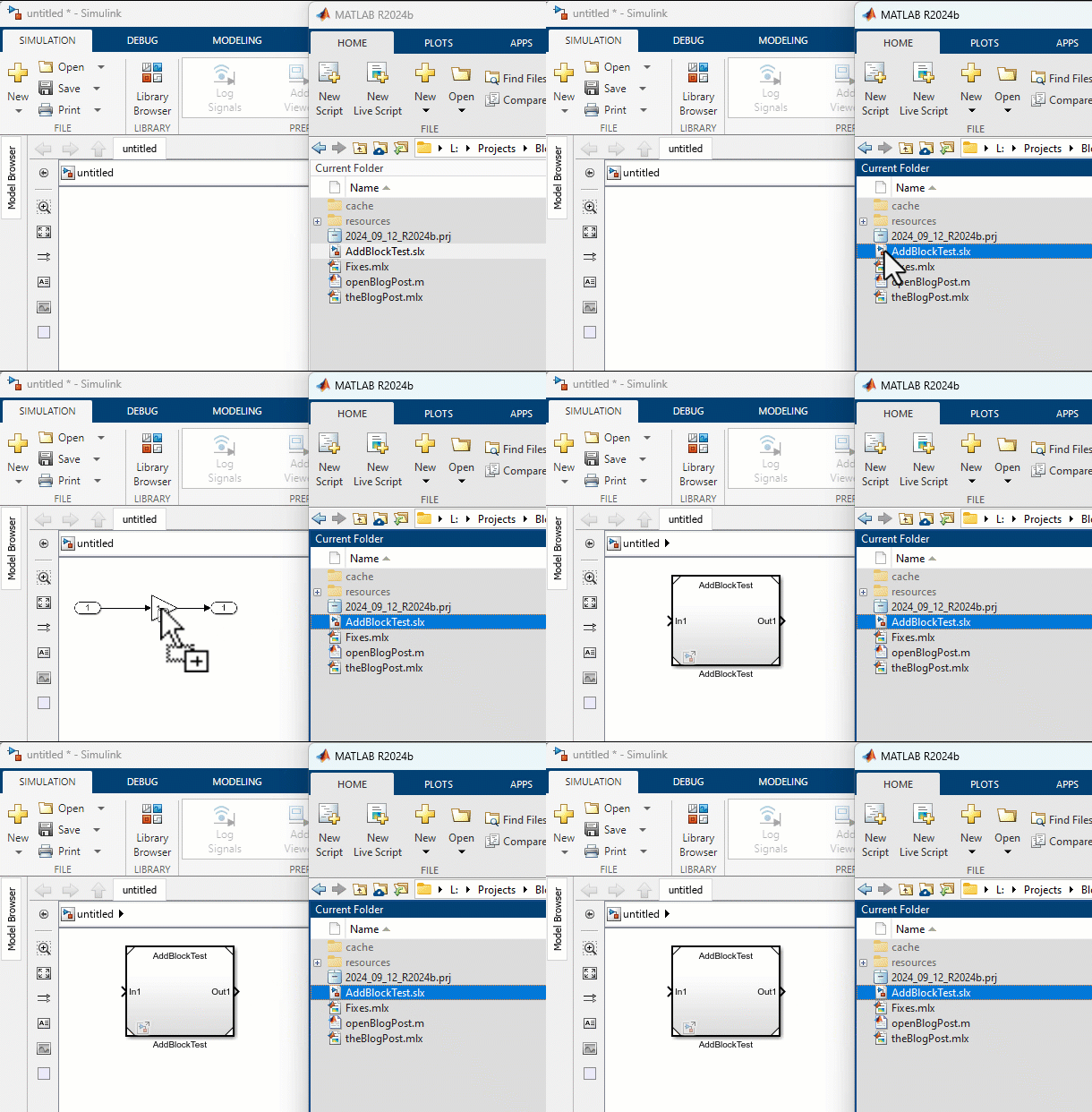
This one is very straightforward: Drag a Simulink file from the Current Folder Browser into a Simulink model, and we automatically insert a Model or Subsystem block referencing it.

Now it's your turn
Look at the Release Notes and let us know what your favorite feature in Simulink R2024b is, or if there are other features you would like me to cover on the blog.
- 범주:
- What's new?


댓글
댓글을 남기려면 링크 를 클릭하여 MathWorks 계정에 로그인하거나 계정을 새로 만드십시오.