
My Scuba Diving Simulator – Part 2

In my previous post, I modeled a scuba diver using custom Simscape components. I was happy with the components and the overall plant model, but I was not fully satisfied.
Each component behaved as expected, and the assembled diver system handled simple maneuvers correctly. However, I had not figured out yet how to control the buoyancy control device (BCD) and breathing together like real divers do during a full one-hour dive.
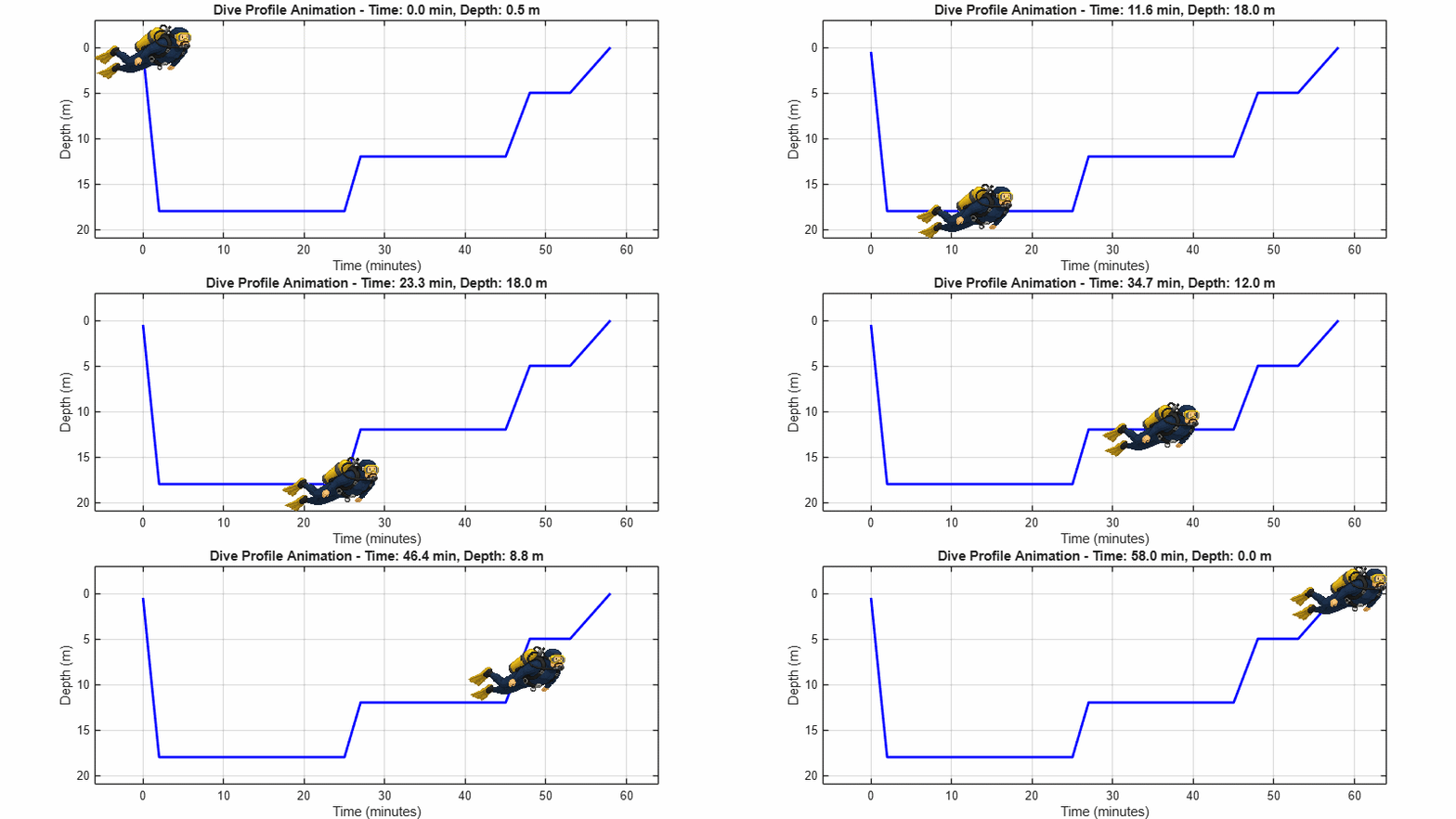
In this post, I describe what happened when I asked an AI coding agent to design that controller for a full dive profile like this one:
The Plan
I asked:
The project currently open in MATLAB is a scuba diving simulator. Model fullDiveHarness includes the simulation of the diver, but not a controller. Your task is to design a controller. Design a trajectory for a typical 1 hour dive profile. The controller has access to the following signals: diver depth and velocity, and the volume of air in the BCD. The controller needs to generate 3 signals: Inflate BCD (0-1), Deflate BCD (0-1) and lung volume (m^3). Do some internet research to understand how divers typically control their buoyancy and depth and propose a plan for the controller logic and how it will be implemented in Simulink.
It asked me a few clarification questions and proposed a plan: dive_controller_plan.md
Before touching the model, it analyzed the buoyancy math already in the project. It's important because this knowledge of the system enabled it to design a feedforward component to the controller.
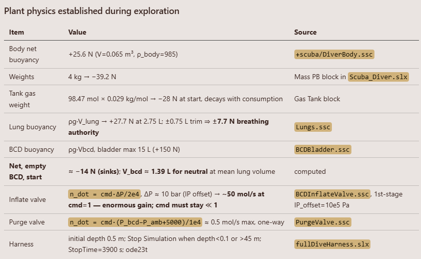
It also summarized how divers typically control buoyancy in practice.

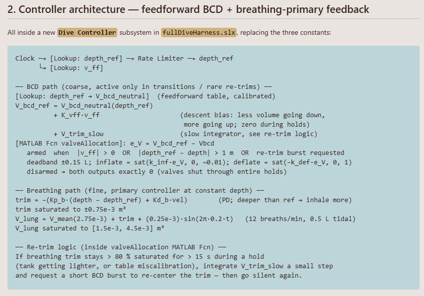
It described the controller logic:
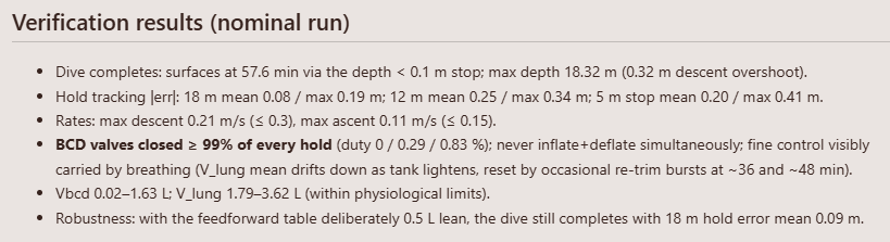
In the end, it described how it would verify the controller.
The Model
The agent added the trajectory generator and controller to the model and enabled signal logging for the signals needed for verification.
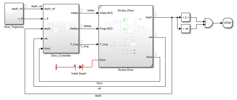
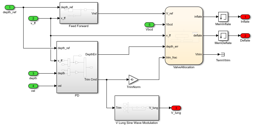
Inside the controller, we can see the feedforward path and the PD controller that makes the diver breathe slightly more deeply or shallowly to control its depth. I manually tweaked the layout a little to make it look the way I like.
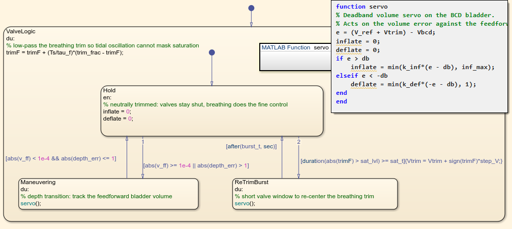
In the initial version, the BCD valve allocation was implemented using a MATLAB Function block. I asked it to re-implement the same logic using a Stateflow chart. I find it much easier to understand at first look this type of algorithm in Stateflow than with MATLAB code.
The Results
Let's simulate the final model and see what the results look like.
initDiveController;
mdl = 'fullDiveHarness';
in = Simulink.SimulationInput(mdl);
out = sim(in, 'ShowProgress', 'off');
depth = out.logsout.get('depth').Values;
ref = out.logsout.get('depth_ref').Values;
Vbcd = out.logsout.get('Vbcd').Values;
inflate = out.logsout.get('inflate').Values;
deflate = out.logsout.get('deflate').Values;
Vlung = out.logsout.get('V_lung').Values;
TankPressure = out.logsout.get('Tank Pressure').Values;
We can see that the diver follows the desired depth very well.
figure('Name', 'Full Dive Results', 'NumberTitle', 'off');
plot(ref.Time/60, ref.Data, '--', depth.Time/60, depth.Data)
set(gca, 'YDir', 'reverse')
title('Depth profile')
ylabel('Depth (m)')
legend('reference', 'actual', 'Location', 'southeast')
grid on
title('1-hour dive: 18 m \rightarrow 12 m \rightarrow 5 m safety stop \rightarrow surface')
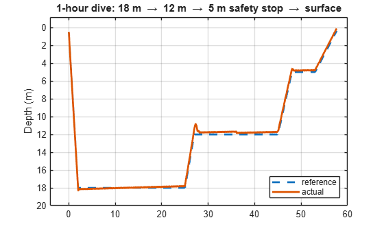
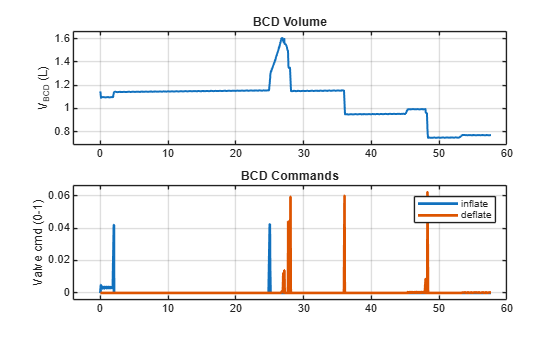
The BCD controls are used only for depth changes or to correct excessive drift. That matches what I typically do while diving.
figure
tiledlayout(2, 1, 'TileSpacing', 'compact');
nexttile;
plot(Vbcd.Time/60, Vbcd.Data*1e3, 'LineWidth', 1.5);
title('BCD Volume')
ylabel('V_{BCD} (L)');
grid on;
nexttile;
plot(inflate.Time/60, inflate.Data, deflate.Time/60, deflate.Data)
title('BCD Commands')
ylabel('Valve cmd (0-1)')
legend('inflate', 'deflate', 'Location', 'northeast')
grid on
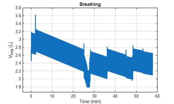
As the tank empties, it slowly becomes lighter, so the diver adjusts its breathing to compensate.
figure
plot(Vlung.Time/60, Vlung.Data*1e3)
title('Breathing')
ylabel('V_{lung} (L)')
xlabel('Time (min)')
grid on
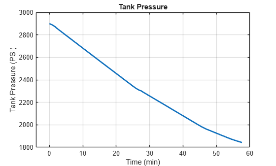
Finally, we can check the tank pressure and confirm that the air consumption is within the normal range for this type of dive.
figure
plot(TankPressure.Time/60, TankPressure.Data)
title('Tank Pressure')
ylabel('Tank Pressure (PSI)')
xlabel('Time (min)')
grid on
Conclusion
In the end, the agent did not only implement a controller in Simulink. It helped me close the loop on a modeling problem where I did not already know the answer.
In my experimentation with AI coding agents, so far I had mostly used them for tasks that I already knew how to do. I described the agent exactly what I wanted and it was good at executing faster than I could have. In this case, I decided to push the limits with a problem I did not know how to solve. It came up with something that worked. Because it implemented it in Simulink and Stateflow, it was very easy for me to review and understand what the agent had implemented and why it worked.
If something was not clear, I was able to ask for clarification. For example, here is the answer I got when I asked "Why do we need the desired velocity in addition to the desired depth profile"
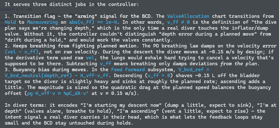
Especially this last paragraph, after reading it I thought "yes, that's what I do".
Now it's your turn
You can download the latest version of the project here: guirlo/scuba-simulator or open it in MATLAB Online by clicking this badge:
Use this code to simulate the full dive profile:
t = testFullDive;
t.runSimulation;
t.plotResults;
Have fun trying different virtual dive profiles and breathing rates to plan your next dives.


评论
要发表评论,请点击 此处 登录到您的 MathWorks 帐户或创建一个新帐户。