
Radar Tracking in Simulink: Variable Size Signals

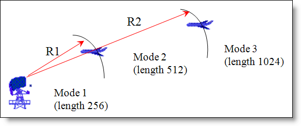
Depending on target ranges, radar systems operate in different modes (different lengths of data etc). Let’s assume we have two planes at two different altitudes. Now, what happens if there is a new plane in sight? Since the number of targets being detected by the radar is now changing, how would you use Simulink to add this plane to its tracking list?
A short and simple answer to this question is: Variable Size Signals.
I’ve read many customer requests wanting to be able to change the dimensions of their Simulink variables while the simulation runs. Be it a radar system which needs to operate in different modes based on its target range to a simple combustion engine that needs to change its frame size based on the number of samples per cycle, each of these system dynamics work with signals whose sizes change during model execution.
Although, earlier I had to tell our customers that Simulink did not have this capacity and you could not change a model’s signals dimensions during execution; with R2009b, Simulink now supports variable-size inputs and outputs in over 40 Simulink blocks.
How does one create a variable size signal?
There are several methods of creating a variable size signal: Switch blocks; Multi-Switch blocks with different input sizes; a Selector block indexing options or custom code blocks (S-functions and Embedded MATLAB blocks).
A common way of generating variable-size signals is to use a Switch block for which each of the input signals differ in size. The Switch Block now allows variable size signals to be passed in as inputs:
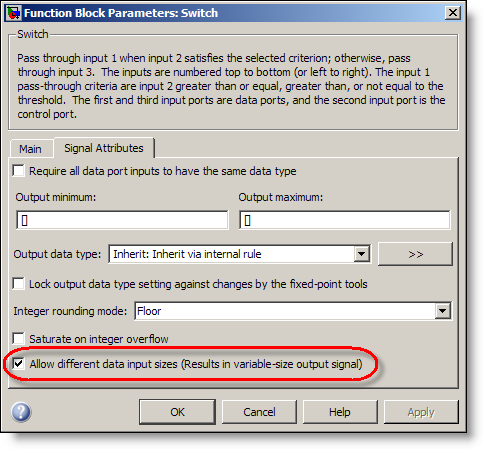
By simply selecting the option “Allow different data input sizes”, you can obtain a variable size output signal whose dimensions change with time.
As an experiment, let us look at a simple demo model “sldemo_varsize_basic.mdl”. This demonstration contains examples of how to use variable-size signals in a Simulink model, and to show what kind of operations you can apply to them.
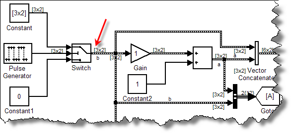
Look at how the Switch block, allowing 2 inputs of different dimensions, can be used for operations like addition, vector concatenation etc.
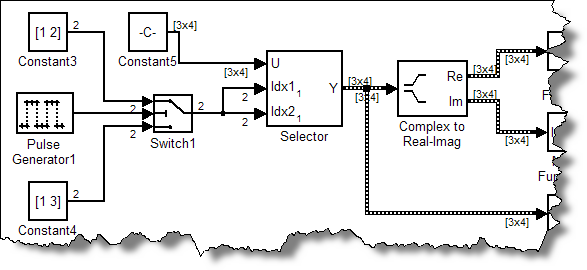
You can also use the “Selector” blocks to create a variable size signal. The Selector block generates as output selected or reordered elements of an input vector, matrix, or multidimensional signal. Using the “Starting and ending indices (port)” indexing option, you can allow inputs of variable dimensions to generate variable size signals.
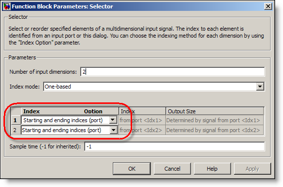
You can use the Selector block to subreferece a matrix as shown below:
How can I get the current dimensions or width of a variable-size signal?
You can use the Probe block to output the width of a signal.
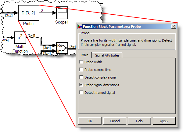
The Probe allows you to visualize and save the signal dimensions and view the I/O and state data for blocks selected. This could also be used in a calculation that requires sample size information.
How can I convert a variable-size signal into a fixed-size signal?
To convert a variable size signal into a fixed size signal, you can use the “Assignment” block. The variable-size signal feeds into the second input port of the Assignment block and can be used to convert the incoming signal into a fixed size signal.
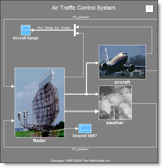
By allowing signal sizes in Simulink models to vary during execution, one can easily model systems with varying environments, resources, and constraints. So, coming back to our radar system, using variable size signals, you can now create a conceptual air traffic control (ATC) radar simulation based on your radar range equation(s):
For more details on how this snazzy feature works, check out the Variable Sizing documentation.
Now it’s your turn
Do you plan to upgrade to R2009b and use variable size signals? Leave a comment here and tell me what you plan to model.
- Category:
- Guest Blogger,
- Signal Processing,
- Signals,
- What's new?


Comments
To leave a comment, please click here to sign in to your MathWorks Account or create a new one.