
Building Models with MATLAB Code
Occasionally I get questions about how to build, modify, and add blocks, to Simulink models using MATLAB commands. In this post, I will to give a basic overview of the common model construction commands.
Contents
Start With a New System
Because you need to refer to the system so often when doing model construction from M-code, I immediately save that off in a variable called sys. The new_system command created the empty model in memory, and you have to call open_system to display it on-screen.
sys = 'testModel';
new_system(sys) % Create the model
open_system(sys) % Open the model
![]()
Adding Blocks and Lines
When I add blocks to the canvas, I specify the position to provide proper layout. The position parameter provides the top left (x,y) and lower right (x+w,y+h) corners of the block. The x and y values are relative to the origin (0,0) in the upper left corner of the canvas; x increases to the right, and y increases down. To keep my layout organized, I use a standard blocks size of 30 by 30, and offsets of 60.
x = 30;
y = 30;
w = 30;
h = 30;
offset = 60;
I like my ports with slightly different proportions, so I define them to be half the height of the other blocks. add_block specifies the source block and the destination path, which defines the block name. Block names must be unique for a given system so add_block provides a MakeNameUnique option. (not used here)
pos = [x y+h/4 x+w y+h*.75];
add_block('built-in/Inport',[sys '/In1'],'Position',pos);
I'll add an integrator block, offset to the right of the inport.
pos = [(x+offset) y (x+offset)+w y+h];
add_block('built-in/Integrator',[sys '/Int1'],'Position',pos)
To connect the blocks, call add_line and provide the system name, source port and destination port. The ports are designated by the 'blockname/PortNum' format. Default line routing is a direct line connection from the source to destination. I prefer to use the autorouting option.
add_line(sys,'In1/1','Int1/1','autorouting','on')

When adding multiple blocks and lines, I group them into add_block/add_line pairs to keep myself organized.
pos = [(x+offset*2) y (x+offset*2)+w y+h];
add_block('built-in/Integrator',[sys '/Int2'],'Position',pos)
add_line(sys,'Int1/1','Int2/1','autorouting','on')

pos = [(x+offset*2) y+offset (x+offset*2)+w (y+offset)+h];
add_block('built-in/Scope',[sys '/Scope1'],'Position',pos)
add_line(sys,'Int1/1','Scope1/1','autorouting','on')

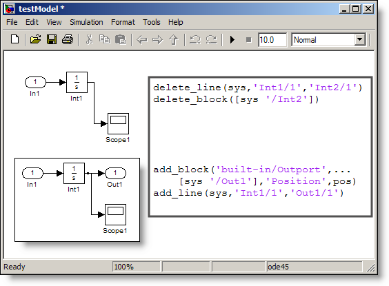
Deleting Blocks and Lines
When deleting blocks, I call delete_line before delete_block. This is the reverse of what I did before. The commands are grouped in delete_line/delete_block pairs. For this example, I'll delete the integrator Int2, and add an outport.
delete_line(sys,'Int1/1','Int2/1')
delete_block([sys '/Int2'])

pos = [(x+offset*2) y+h/4 (x+offset*2)+w y+h*.75];
add_block('built-in/Outport',[sys '/Out1'],'Position',pos)
add_line(sys,'Int1/1','Out1/1')
Replacing Blocks
Sometimes you don't really want to delete a block, you are just going to replace it. replace_block gives you the capability to replace all blocks that match a specific criteria. I reccommend carefully reading the documentation to better understand this function.
replace_block(sys,'Name','In1','built-in/Sin','noprompt');
set_param([sys '/In1'],'Position',[x y x+w y+h],'Name','Sine Wave');

[t,x,y] = sim(sys);
plot(t,y), ylim([-.5 2.5]), grid on
Now it's your turn
Do you use model construction commands? Why doesn't the cosine on that scope cross below zero? Leave a comment here with your thoughts.
- Category:
- Commands,
- Fundamentals


Comments
To leave a comment, please click here to sign in to your MathWorks Account or create a new one.