
How do you think about virtual buses?
Today I present for your reading pleasure a continuation of our discussion on mux and bus signals. Last week we looked at the advanced uses of Mux Blocks. This week I want to discuss the mental model of virtual bus signals.
We start with a simple bus model
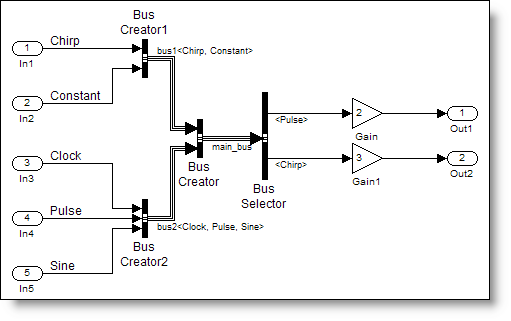
I have slightly modified the busdemo.mdl example that ships with Simulink to make my simplebusdemo.mdl. Buses are used to route signals around complex diagrams, and this model is not complex, so bear with me. In addition, bus signals usually pass through levels of hierarchy, but for convenience, I am keeping everything at a single level.
The mental model of the bus
In a previous post, I talked about the mental model of the bus as a tie-wrap of wires. I imagine the rainbow bundle of wires gathered together at the bus creator, and just the wires I am interested in emerging from the bus selector. Virtual bus signals are simply a graphical convenience and do not change the behavior of the model.
What do you mean by a virtual bus?
When you look at the bus creator block, you will notice that there is a box to check labeled "Output as nonvirtual bus". Unless this is checked, a virtual bus signal is output.
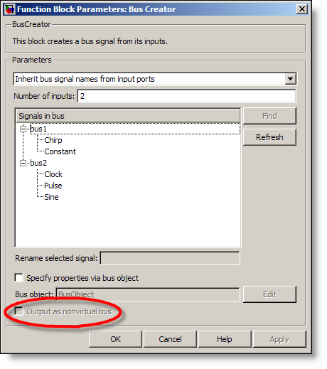
The Bus Creator and Bus Selector dialog show the contents of the bus by signal name. These signals (the individual colored wires) are arranged hierarchically by their connections to the Bus Creator blocks. The Bus Creator blocks do not actually change the signals, and so we can call these virtual buses. The diagram represents the bus as we draw it, and this keeps everything nice and organized for us.
What does Simulink do with the bus?
Simulink needs to know the actual sources that feed into the bus, and the destination blocks that are connected to the outputs of the Bus Selector. Simulink gets this information in the first part of the simulation process during Update Diagram. Before the model runs, Simulink compiles the diagram into an internal representation. This compile process is part of Update Diagram. You can force Simulink to compile the diagram through the menu Edit->Update Diagram, or use the hot-key Ctrl-D.
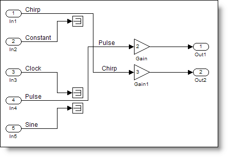
Update diagram analyzes the model to make sure that it conforms to the semantics of Simulink. I have not always thought of Simulink as a programming language, but when I draw the diagram, I am actually programming! The compiled internal representation removes any unnecessary stuff in the model. In our model, there are five inputs and two outputs. To calculate the outputs we only need the Pulse and Chirp signals. So what happens to the other signals?
When you update the diagram, it is equivalent to a wiring of the actual sources directly to the blocks consuming those signals. Simulink does not include the virtual bus in its internal representation. We can imagine the internal Simulink representation for our simple bus model, after update diagram:
Virtual buses are efficient
Virtual bus signals are efficient because Simulink optimizes the unused signals out of the model. For many of the large models I work with, virtual buses keep the diagram organized and do not add overhead in the model. If you go back to our mental model of the rainbow bundle of wires, the unused signals are essentially like wires that only connect at one end. They might be a part of the bundle, but there is nothing connected at the destination. Simulink only needs to keep track of the wires that run from a source to a destination.
When I want to see another view on the internal representation in Simulink, I use the Real-Time Workshop to generated C-code. The integration of Simulink and Real-Time Workshop allow you to convert the model in to C-code that is appropriate for running on a real-time embedded system.
If you did not believe me that Simulink gets rid of the virtual bus, look at the C-code. There is no evidence of bus signals here:
   27     /* Outport: '<Root>/Out1' incorporates:
   28      *  Gain: '<Root>/Gain'
   29      *  Inport: '<Root>/In4'
   30      */
   31     simplebusdemo_Y.Out1 = 2.0 * simplebusdemo_U.Pulse;
   32
   33     /* Outport: '<Root>/Out2' incorporates:
   34      *  Gain: '<Root>/Gain1'
   35      *  Inport: '<Root>/In1'
   36      */
   37     simplebusdemo_Y.Out2 = 3.0 * simplebusdemo_U.Chirp;
All that remains are the connections from the Pulse and Chirp inputs (part of the input signals structures model_U) to the gain blocks (which have been in-lined in the code) to the outputs.
Back to basics
I am eager to get into nonvirtual bus signals; however, I think it is important to review the basics before we jump into the advanced. Did you already know this? Does this fit with your mental model of virtual bus signals? Leave a comment and tell me about it.
- Category:
- Signals


Comments
To leave a comment, please click here to sign in to your MathWorks Account or create a new one.