Follow the Bouncing Ball
In my last post about the Continuous Time Integrator, I talked about the bouncing ball model sldemo_bounce. Amin commented:
Hi Seth!
Is it necessary to rest the position integral in the bouncing ball demo?
I get same result without reset the integral and set the internal initial condition to 10.
I forwarded this to my friend Fu who works on developing the solvers. Fu said:
Hi, Seth:
The bouncing ball can be modeled in many ways. Actually if you check an old version of MATLAB, you can find another implementation of this model.
I looked back at the R13 bounce.mdl demo model, and found a different implementation.

There are many design decisions you have to make building a model. I started with the R2008a version and explored what Fu means.
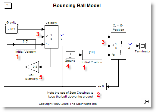
The R2008a demo model: optimized for readability
This model ships with Simulink (sldemo_bounce.mdl).

It has many nice qualities. I can read the diagram and see:
- Initial conditions of the velocity and position integrators
- There is a lower limit on the position integrator of 0
- This lower limit triggers resets in the velocity and position states
- The position state resets to zero (ground)
- The velocity state resets to -0.8*V (80% elastic rebound)
As Amin found out, you can modify this model and still get the same answer.
A slight change: removing the position reset
Just like when optimizing M-code, you might want to remove unnecessary parts of your design. If we do not need to reset the position state, because of the limit, we can remove the connection to the reset port.

I had to use the output of the position integrator for the reset signal on the velocity state. This is because state ports can only be used to break algebraic loops or to "hand-off" states between systems.
Using the saturation port to trigger state reset
The continuous time integrator has an optional saturation output. Instead of deriving a triggering signal from the position by calculating when Z<=0, we could use the saturation signal.

This signal (1 above) is zero when the position is within the bounds of the limits (0 inf), one when it saturates on the upper limit and minus one when it saturates on the lower limit. The transition from 0 to -1 is a falling zero crossing and it can replace the calculated reset signal. We have to change the velocity integrator to reset on falling zero crossings (2 above).
Simulink Golf: using the fewest base blocks
You may have heard of MATLAB Golf. This is the game/pastime where you attempt to write a complete algorithm with the fewest number of characters. A similar game can be played using Simulink.

That is my attempt at a model with the fewest base blocks (not counting virtual blocks like mux and selectors). I have to admit I was just playing around when I built this. It is much harder to understand how all the dynamics fit together, and it would be harder to upgrade and maintain. I combined all the states into a single integrator (1) and had to add the selector block (2) to pull out the position state.
Summary
Your choice of implementation in Simulink involves many factors. In the R2008a demo model, the emphasis is on readability. You can understand most of the model just by looking at the diagram, and it doesn’t require a lot of clicking to find the parameters. I believe this is the most important measure of design in Simulink.
To make a model readable, follow the same general rules as when writing good code. Two of the design rules that come to mind are:
- Avoid terse constructs (like Simulink Golf)
- Add comments to explain how features of the model work
Now it’s your turn
What do you consider when making design decisions? Leave a comment here to share your process with the community.
- カテゴリ:
- Modeling


コメント
コメントを残すには、ここ をクリックして MathWorks アカウントにサインインするか新しい MathWorks アカウントを作成します。