
Refining the Output of a Simulation
Today I am pleased to share a post from regular guest blogger, Guy Rouleau. Enjoy!

I often use Simulink to model the dynamics of simple systems. In most cases, the Simulink default settings provide a good tradeoff between accuracy and simulation speed. These settings usually allow me to observe the signals I am interested in.
I recently ran into situations where I needed to change the default Simulink settings to observe the signals I was expecting.
Let’s begin by a very simple case: Simulating a 100Hz sine wave of amplitude 1 for 10 seconds
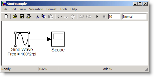
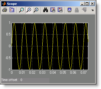
With the default Simulink settings, the Sine wave observed on the scope is the following:
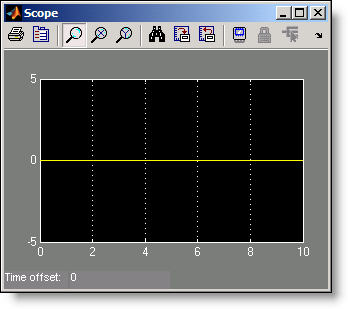
Before screaming “Simulink is broken!”, let’s look at the warning displayed at the MATLAB command prompt when playing this model.
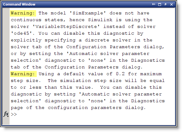
The first warning mentions that the selected solver "ode45" is replaced by the Variable-Step Discrete solver. The second warning says that Simulink will use a default step size of 0.2 sec.
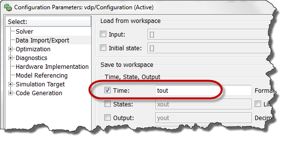
The combination of these two warnings results in Simulink evaluating the Sine wave at time [ 0 0.2 0.4 … 9.8 10 ] where it’s value is always zero. To observe the Sine wave properly, a very useful option is to refine the output:
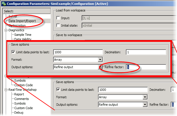
By setting an appropriate value for the refine factor, it is possible to observe the expected Sine wave. This is the result with a refine factor of 250:
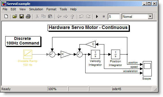
Now you might think, "Interesting, but I never create models with only a Sine Wave." I agree, so let’s look at a more realistic simulation and model a servo motor commanded by a discrete controller. Our Simulink model looks like:
Using the default settings, the Scope block displays the position, velocity and acceleration as:
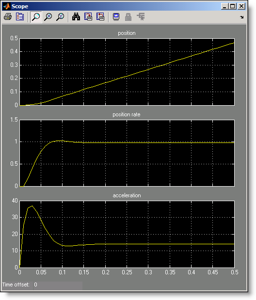
Attentive eyes probably noticed that after 0.2 second, the acceleration signal seems constant around a value of 14, while the velocity signal is also constant at 1. Since the slope of the input ramp is 1, we can conclude that Simulink computes the velocity value accurately, but why isn’t the acceleration zero as one could expect?
Maybe we should refine the output. Setting the refine factor to 4 provides a better resolution in time and shows the real behavior of the system.
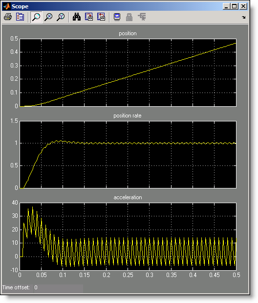
In that case, it shows that the servo motor acceleration signal oscillates when submitted to the 100Hz discrete steps of the command coming from the computer.
What else should we know about the refine factor?
- To get smoother output and have a better time resolution, it is much faster to change the refine factor instead of reducing the step size.
- When the refine factor is changed, the solvers generate additional points by evaluating a continuous extension formula at those points.
- The refine factor applies to variable-step solvers and is most useful when you are using ode45.
- Usually a value of 4 produces much smoother results.
Now it’s your turn
Do you ever use refine factor? Leave a comment here and share your experience.


评论
要发表评论,请点击 此处 登录到您的 MathWorks 帐户或创建一个新帐户。