
How to model a hard stop in Simulink
Since R2010a, the Simulink Library includes a block named Integrator, Second Order.

In my experience most people do not know about this block. Let's look at an example were the Integrator, Second Order is especially useful.
The problem: Modeling a Second-Order system with saturation
More often than I would like to admit, I have seen users struggling to simulate Second-Order systems with saturation. For example this could be a cylinder with hard position limits, or a rotating shaft restricted between two angle limits. The model could look like:
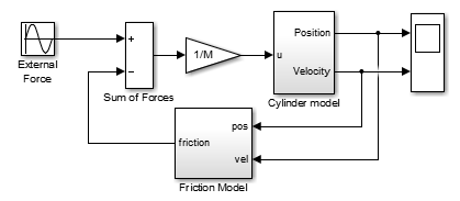
Typically, users will try to model the cylinder using two Integrators in series and build a logic attempting to reset/disable/saturate them to obtain the correct relation between input force or torque, velocity and position. Let's look at a few examples highlighting why this is not as easy as this looks like.
Attempt 1: Inconsistent position and velocity
As a first try, many users will try to model the cylinde using something like this:
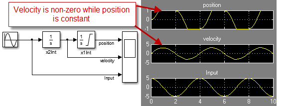
In this case, the position saturates at the limits. However notice that when the position is constant, the velocity is not always zero, which is definitely wrong.
Attempt 2: Disabling the integration
To fix the fact that position and velocity are not consistent, one might try the following modification:
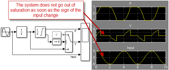
If this modification fixes the inconsistency by setting the velocity to zero when the position is saturated, there is still a problem. When the position is saturated, the first Integrator keeps integrating. Because of that, the system does not go out of the saturation as early as it should.
Attempt 3: Almost there... but not yet
To make the system go out of the saturation at the correct time, we need a logic to control the integration of the first integrator based on the input and position. This can look like:
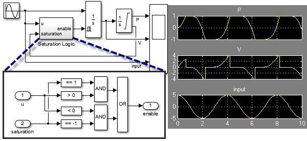
Now we have something that is nominally correct and mostly satisfies the systems equations. However the model has inefficiencies due to unnecessary zero crossings, and a subtle inaccuracy.
If we look closely at the series of events when the system goes out of the saturation, we can see:
- A zero-crossing event is detected when the sign of the input signal changes
- The first integrator is enabled
- One time-step later, the output of the first integrator becomes non-zero
- The second integrator gets out of the saturation (a little bit later than it should), triggering a second unnecessary zero-crossing event.
Attempt 4: OK, I see what you mean... but I am sure there is a way!
If you are like me, at this point you are probably telling yourself: There's got to be a way!
Actually, it is possible to use the State Port of the position integrator and obtain a solution that is both efficient and numerically correct. To make the logic clearer, I used a continuous-time Stateflow chart:
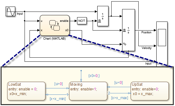
But there is a catch... if you look at this implementation carefully, you will notice that the relation between the input signal and the position output signal is directfeedthrough. This means that when you will try using this cylinder model in a realistic model including a feedback loop like the one at the beginning of this post, this will result in an algebraic loop.
The Solution
I hope you are now convinced that the Second Order Integrator is the way to go for this use case!
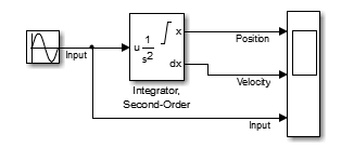
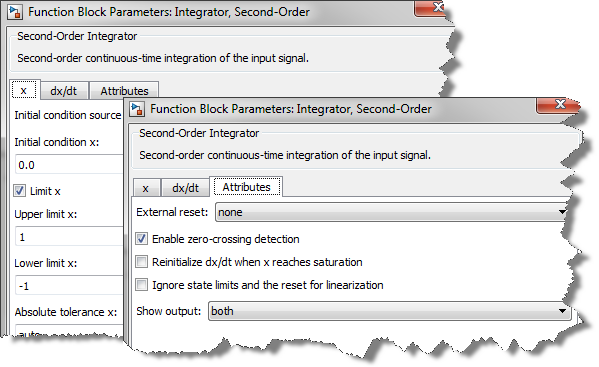
All I have to do is enabling the Limit x option, and ensure I leave the Enable zero-crossing detection in the block dialog
After logging data and using the Simulink Debugger, we can see that this implementation using the Second Order Integrator generates 50% less zero-crossing events and can be solved in 25% less time steps than the implementation showed at step 3 above. In a large model, this can have a significant impact on performance.
Now it's your turn
Give a look at the Simulation of a Bouncing Ball example for a similar analysis comparison between two Integrator blocks and the Second Order Integrator block.
For a more advanced example using the Second Order Integrator, I recommend looking at: Modeling a PWM Driven Hydraulic Servomechanism. This model simulates an hydraulic cylinder, and a solenoid valve, both implemented using the Second Order Integrator.
Try the Second Order integrator and leave us a comment here.
- Category:
- Modeling


See Also
-

A New First Order Hold!
Blogs
-

Follow the Bouncing Ball
Blogs
-
-
-

Comments
To leave a comment, please click here to sign in to your MathWorks Account or create a new one.