
My Mental Model of a Model
When you are new to something, it always helps to get a mental picture of how that something works. Since I learned Simulink over 10 years ago, I have developed my own mental model of Simulink models. Today I want to present a mental model for the three basic components in Simulink block diagrams, ports, blocks and signals.
Something Familiar
A good mental model is something to which you are already familiar. I like to compare Simulink diagrams to programs written in a procedural language like MATLAB or C. My favorite is MATLAB, so that is usually how I think.
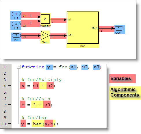
Ports
Ports are the input and output arguments for the function.
Blocks
When I think about blocks, I think of them as algorithmic components of the programs. A block like the Gain or Product is a function that operates on inputs and produces an output.
Signals
Signal lines pass the value output from one block to the next block. I think of signal lines as the variables in a program.
Generating Code
With my intuition in hand, I read the generated code so I can compare and refine my mental model. The result is here:
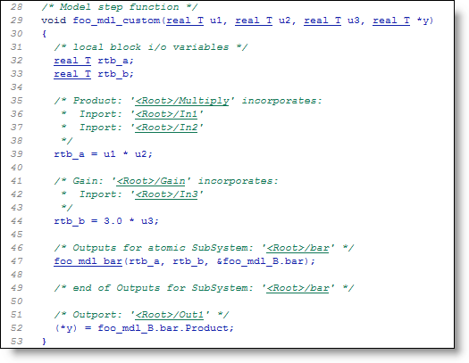
In this case, I made a couple tweaks to the code generation settings for readability and interface.
What do you think?
How does your mental model of a block diagram compare to mine? Leave a comment here and share it with me.


See Also
-

My First Debugging Steps
Blogs
-
-
-
Comments
To leave a comment, please click here to sign in to your MathWorks Account or create a new one.