How to Learn Model-Based Design using Simulink
Learning Model-Based Design using Simulink
By Guy Rouleau

I consider myself lucky to come from a school where we learned and applied Model-Based Design through projects. During my graduate studies, I had the opportunity to teach a class I took as an undergrad titled "Mechatronics Project", where the students had to control a wheeled robot. The project included:
- Planning: The students had to make a high level "interaction diagram" of the final system. In other words, they began by creating a Simulink model with empty subsystems to describe the interactions between the robot components.
- Measure the robot motion: Students could use an FPGA to process encoder pulses. As mechanical engineers, the students were very happy to avoid the complexity of FPGA programming and directly use Simulink to generate the FPGA code.
- Create a plant model: They implemented the robot’s equations of motion in Simulink and experimentally characterized important parameters, like friction.
- Control the robot motion: They implemented a PID with op-amps and resistors on a breadboard. I cannot imagine the amount of fuses we saved by designing the controller using Simulink, wiring the breadboard only once.
- Generate the trajectory: For this part, students had to program a microcontroller in C language. They could have used Simulink here too, but it would have made their life too easy!
At the end of the semester, each team had a validated working robot and an equivalent simulation.
Update
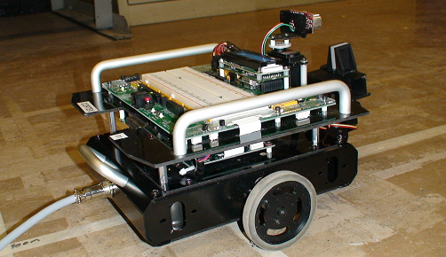
I just received a picture of the robot used in this class. Here is what it looks like:

How did you learn Simulink and Model-Based Design? What's the coolest project you have worked on? Leave a comment here to tell us about it.


评论
要发表评论,请点击 此处 登录到您的 MathWorks 帐户或创建一个新帐户。