Wrong Answers and Gimbal Lock
 By Guy Rouleau
I received a request last week where the code generated using Real-time Workshop was giving different answers from the original simulation. This type of requests is the one that scares me the most, because the goal of Real-Time Workshop is to generate a code equivalent to a Simulink model.
Let's see how I approached this challenge!
1. Reproducing the issue
The first thing I do when I have a “different results” case is to confirm what the user reports. I built the model using the GRT target and compared the logged data. They are different!

2. Understanding the system
The model had an architecture similar to the NASA HL-20 demo shipping with the Aerospace Blockset.
My mental representation of this model looks like:

This architecture is used in many domains where the motion of a body in space must be simulated, for example robotics and aerospace.
3. Understanding the results
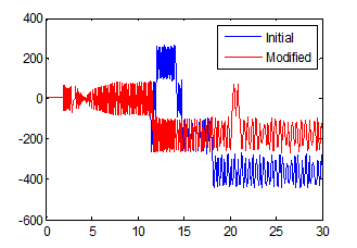
Let’s take a closer look at the different data and zoom on where they diverge:

This signal represents an orientation oscillating between +90 and -90 degrees and we see that there is a clear switch around -90 degrees.
4. Guessing something
This is when Seth passed by my office. Based on the indices we had, he suggested that the model might be very sensitive to numerical perturbations. It is well known that floating point round off can cause small differences on the order of eps between generated code and simulation. But when a system is very sensitive and unstable, a difference even as small as eps can grow into completely different results.
5. Testing the hypothesis
If the model is sensitive to numerical perturbations, modifying the initial states by a random value on the order of eps will affect the results significantly. I tested it, and it changes the simulation results significantly. What I notice is that every time I run the simulation using a new random value, the “switch” around 90 degrees happens at different times.

6. Finding a solution
Now that we know that the model is numerically sensitive, it would be great to fix it!
Having generated six degrees of freedom trajectories for robotic manipulators in the past, I remembered learning somewhere that the Euler angles representation of orientations has a singularity, known as the gimbal lock.
In the 6Dof Euler Angles block, the angles are obtained through integration of the Euler Angles derivative, which is computed using this equation:

where [p q r]T is the body-fixed angular velocity vector and  is the the rate of change of the Euler angles. In this equation, when theta is close to 90 degrees the matrix becomes badly scaled and causes the numerical sensitivity described above.
An alternative to integrate the body motion is to compute the rate of change of rotation quaternions instead. :

Quaternions have a lot of advantages: They are numerically more stable than rotation matrices and avoid the gimbal lock problem of Euler angles.
7. Validate your solution
In the Simulink model I replaced the Euler Angles implementation:

by the quaternion representation:

I tested the solution by comparing simulation with numerical perturbation and generated code. Now simulation results and generated code results are matching as expected!
Now it’s your turn!
What is your process of investigation when Simulink does not give the results you expect? Leave a comment here


评论
要发表评论,请点击 此处 登录到您的 MathWorks 帐户或创建一个新帐户。