
Zero-Crossing Detection… what are your options?
When using Simulink variable-step solvers, zero-crossing detection is very useful to capture events accurately. However for some equations, configuring zero-crossing detection can be challenging.
Last week I received the following question and example model:
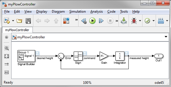
In the attached model, I implemented a basic bang-bang controller for a plow. Using a Sign block, I generate a 1 for the plow to go up, -1 to go down and 0 to stop. The problem is that the plow never seems to stabilize around zero. Can you help me understand why?
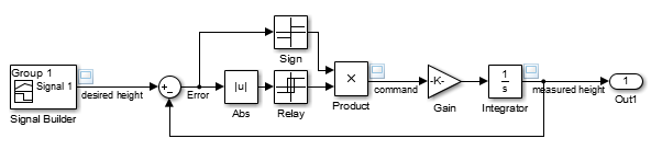
Here is an image of the model:
Nonadaptive zero-crossing detection
With the default settings, this model errors out as soon as we try to give a non-zero command with the following error:
At time 1.0000000000236877, simulation hits (1000) consecutive zero crossings.
Consecutive zero crossings will slow down the simulation or cause the simulation to hang. To continue the simulation, you may
1) Try using Adaptive zero-crossing detection algorithm or 2) Disable the zero crossing of the blocks shown in the following table.
--------------------------------------------------------------------------------
Number of consecutive zero-crossings : 1000
Zero-crossing signal name : Input
Block type : Signum
Block path : 'myPlowController/Sign'
--------------------------------------------------------------------------------
You can turn off this message by using the MATLAB command:
set_param('myPlowController','MaxConsecutiveZCsMsg','none');
This error is relatively simple to understand by looking at the ideal plant model (an Integrator block) and the switching logic. If the plow position is slightly negative, the controller makes it move upward, leading to a positive error. The controller sees this positive error, makes the plow go down, bringing us back to our original state .
With zero-crossing detection enabled for the Sign block, Simulink will detect that we crossed zero and try to reduce its step-size to capture this transition accurately. But here, reducing the step size will not help. The step size can be a small as possible, a small negative error will always lead to a jump on the positive side, and vice-versa.
Let's try the suggestions offered by the error message. What suggestions? If you didn't read the error message, go back and read it now.
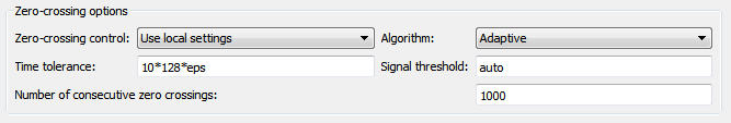
Suggestion 1: Adaptive zero-crossing detection
In the solver section of the model configuration, we can try selecting adaptive zero-crossing detection. This will dynamically activate and deactivate zero-crossing bracketing, helping with models that exhibit strong chattering.
With this setting the simulation completes, but the variable step solver takes way too many steps when it is not needed, and the position error is too large.
The reason is that the adaptive algorithm encountered multiple consecutive zero-crossings for the Sign block and decided to disable zero-crossing detection for this block. Once this is done, the solver takes larger steps and gives inaccurate results.
Let's try suggestion 2 from the error message.
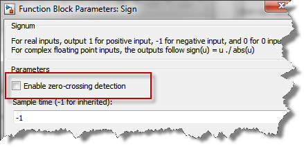
Suggestion 2: Disabling zero-crossing
The second suggestion from the error message is to disable zero-crossing detection for the problematic block.
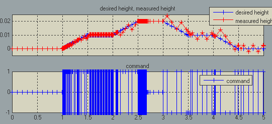
In this case, the tracking is significantly better because the solver uses the state of the integrator to limit its step size, but we see a lot of switching happening when the plow desired height is constant.
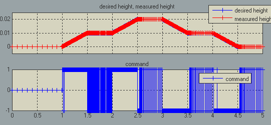
The main problem here is that it is impossible for the Simulink engine to stop exactly on the zero value of the Sign block with this system. With the equations involved, Simulink can take very small steps around zero, but will not stop exactly on it. This not what the Sign block is designed to do.
Possible solutions
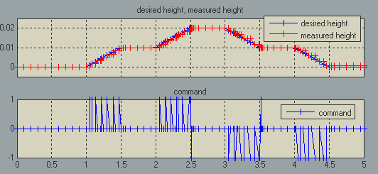
If we want a system that can be simulated efficiently using a variable step solver, we have to modify the equations. If we want to keep the plant as it is, we need a controller with a logic that will stop when the error is within a certain range around zero. For example, we could use a Stateflow chart or a block with hysteresis like the Relay block:
In this case, the plow stops moving when the command is fixed and the zero-crossing detection helps ensure that the solver takes appropriate steps when needed.
Now it's your turn
If you have some interesting plowing or zero-crossing stories to share, leave a comment here
- Category:
- Debugging,
- Modeling,
- Performance,
- Simulink Tips


Comments
To leave a comment, please click here to sign in to your MathWorks Account or create a new one.