
Generating Reports for a Simulink Model including LaTeX Equations
Sarah first lists different options available in Simulink to document your design, and concludes with a new capability added recently: Using LaTeX equations in Simulink Notes, which allows you to automatically produce reports, thanks to the Simulink Report Generator API for notes!
Introduction
While the functional behavior of models we create is usually the star of the show, anyone who has had to review, test, or maintain these knows that documentation can be the real hero. Simulink offers many ways to capture information along with a design, allowing you to create documentation as you go; here are a few examples:
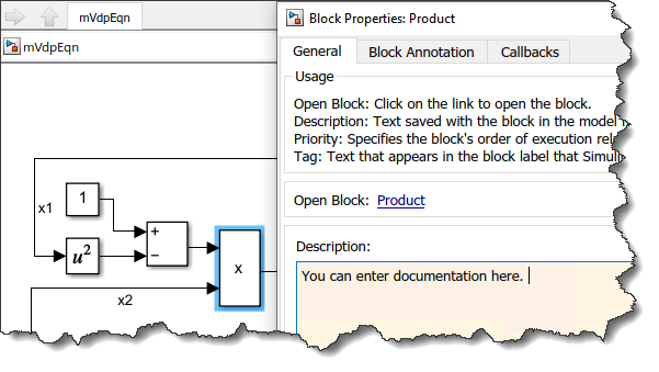
Block Description
If you right-click on any block and select "Properties...", the General tab offers a "Description" field.
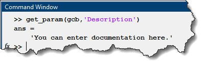
This can also be get/set programmatically:
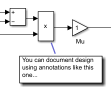
Annotation
Double-clicking in the Simulink canvas allows you to create annotations. Once the annotation has been created, you can click on its edge and attach it to a block. It is also possible to create annotations programmatically
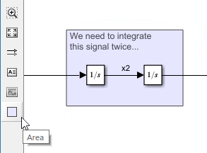
Area
Starting from the left toolbar, it is possible to create areas. In addition to allowing you to type a description, an area allows you to move all the blocks inside it as a group.
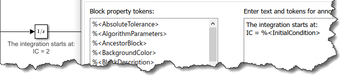
Block Annotation
The Block Properties dialog allows you to create block annotations. In block annotations, you can use tokens to display the value of bock parameters.
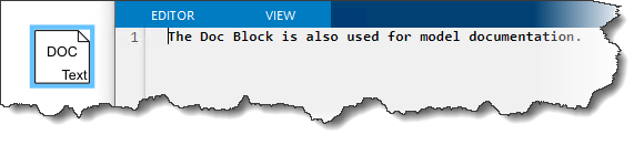
Doc Block
The DocBlock is another option to document a Simulink model. Add the block to any Subsystem, double-click on it and start typing. If you open the mask parameters for the DocBlock, you can configure it to open the note as either text, RTF or HTML.
Equations
Much of what we model in Simulink is based on equations. While Simulink is great for visualizing the flow of data through algorithms, sometimes it’s a lot easier to understand what’s going on if you can just see the equation that is being modeled.
While you might be used to seeing equations typed in plain text, it can be much easier to understand when rendered the way you might write it out by hand -- this is why so many engineers and scientists love TeX and LaTeX! And while MATLAB has long provided ways to interpret TeX and LaTeX syntax, including it everywhere you might have documentation associated with a Simulink design can be tricky.
For example, you can create Simulink canvas annotations with equations:
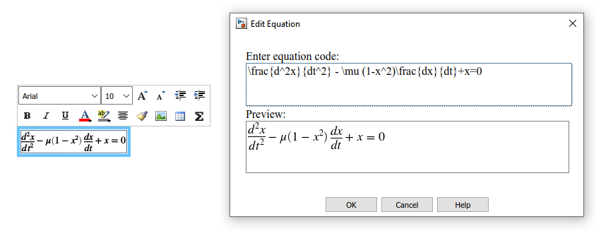
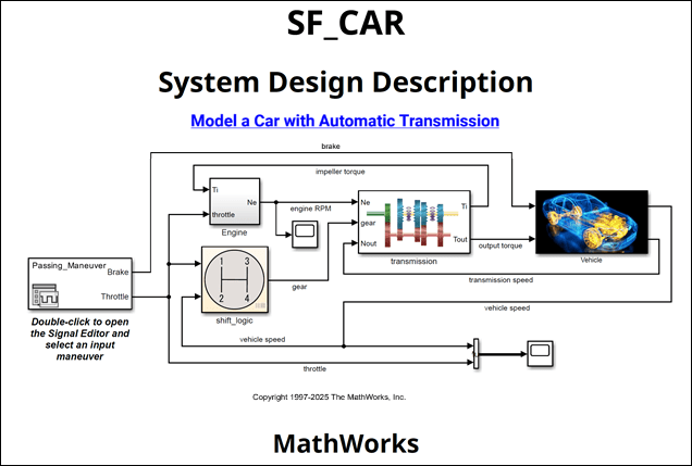
However, it’s not very straight-forward to get this type of annotation into a report that might be needed as design documentation, such as a System Design Description (SDD). A SDD is part of a high-integrity certification workflow, such as for DO-178C, so this can be more than just a minor annoyance.
Model Notes
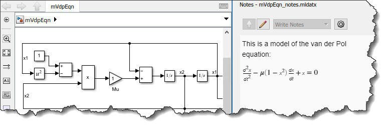
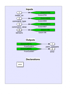
Notes are another way to create documentation for your model. Notes are saved in a separate file from your model, unlike the other annotation techniques shown above. Notes are context-aware and can contain and display content for subsystems throughout your model hierarchy. And, notes can include equations!

When someone else will open the model, this will look like:
Report Generation
Now it’s time to bring all this together… information that is sensitive to its Simulink context, includes mathematical equations and formatting, and can be used in automatically generated, portable, and complete design documentation – behold, the Simulink Report Generator API for notes!
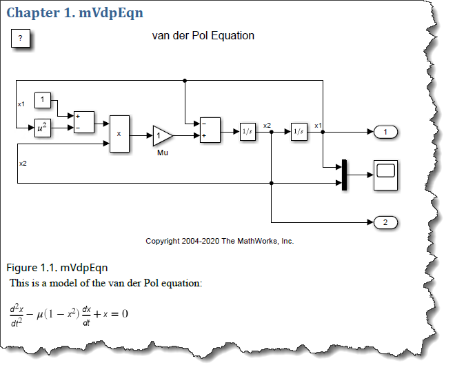
For the model in the above screenshot, this code will generate a PDF with a screenshot of the subsystem followed by the Note, including equations.
model = "mVdpEqn";
open_system(model);
import mlreportgen.report.*
import slreportgen.report.*
import slreportgen.finder.*
rpt = slreportgen.report.Report(model + "_Notes_Report","pdf");
open(rpt);
titlepage = TitlePage("Title",model);
add(rpt,titlepage);
toc = TableOfContents();
add(rpt,toc);
finder = DiagramFinder(model);
while hasNext(finder)
system = next(finder);
ch = Chapter("Title",system.Name);
add(ch,system);
notes = Notes(system);
add(ch,notes);
add(rpt,ch);
end
close(rpt);
rptview(rpt);
Now it's your turn
Are you leveraging Simulink Report Generator and Simulink Notes to document your design and automatically generate reports? Let us know in the comments below.


コメント
コメントを残すには、ここ をクリックして MathWorks アカウントにサインインするか新しい MathWorks アカウントを作成します。