
Springtime and R2008a
I am eager for winter to release its icy grip on New England. Fortunately, change is in the air and spring is around the corner. At work, the big change is the new release of MATLAB. After installation I immediately notice the slight differences in the UI.
The new release of MATLAB and Simulink products went live for download at the beginning of this month. You can read about some of the changes to R2008a in the release notes. Here are some of my favorites:
- Simulink has a new library browser available on all supported platforms! The graphics are smoother, and the search capabilities have been enhanced. Take a look:

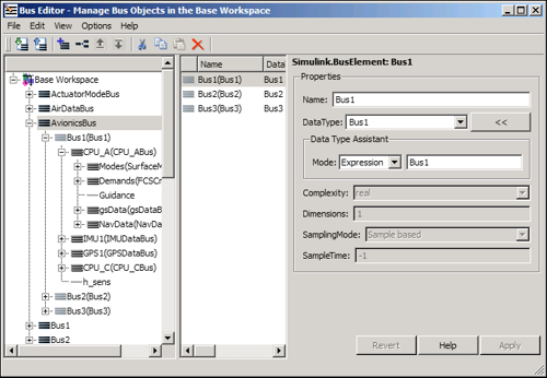
- The bus editor has been re-designed. The tree displayed in the left pane now shows the full bus hierarchy under each bus, instead of just the immediate child elements. I have been frustrated in the past when I forgot to save the changes to my bus objects back into a MAT-file for future sessions. The new editor now has load and save capabilities built in.
- In R2008a model reference rebuilds have become more efficient. Parent models will only rebuild if they need to because of an interface change in their child models.
- The limit on the number of Accelerator mode reference models in a model hierarchy has been lifted on Windows.
- Bidirectional traceability has been added to Stateflow Charts and Embedded MATLAB functions. This used to only be available for Simulink blocks.
- More simulation data can be logged on 64-Bit platforms. The limit is now up to 2^48-1 bytes (one byte shy of 256 TB!) in each field of the logging Structure, Timeseries or each Array variable! The limit on earlier releases is about 2 GB per variable.
- New autosave options are available for Simulink models to help guard against loss of work.
- Level-2 M-file S-functions are now easier to write with the new basic template: msfuntmpl_basic.m.
- There is a new zero crossing algorithm for use with the variable step solvers. The adaptive zero crossing mode better handles systems which exhibit chatter.
- The Desktop Team should get some credit for enhancing the MATLAB editor to provide TLC syntax highlighting.
- The Real-Time Workshop Embedded Coder has new AUTOSAR compliant code generation capability, and there are even some demos to go along with it.
- R2008a has improved MISRA-C compliance for matrix math utilities and lookup block utilities.

Over the next few months, as the spring flowers bloom (for those of us in the northern latitudes), I will highlight many of these new features.
These are some of my favorite enhancements to Simulink products. Have you activated your new copy of R2008a? What do you see in the release notes that you want to try out?
- Category:
- What's new?


Comments
To leave a comment, please click here to sign in to your MathWorks Account or create a new one.