
Advanced Maneuvers using Mux and Demux
Last week I started a discussion of mux and bus signals. Our mental model of the mux signal is a vector. The Mux and Demux Blocks can do more than just combine and break apart the elements of a vector. This week I want to go a level deeper and talk about the advanced maneuvers using Mux/Demux Blocks.
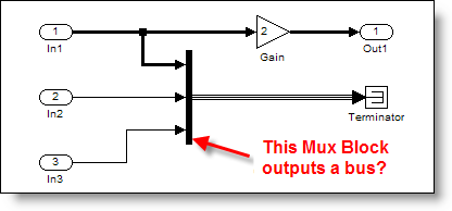
Mux Blocks as specifications
The first thing I want to show you is how to use the Mux Block to specify additional information about the signal dimensions at its ports. Instead of just putting the number of ports, you can specify the width of each signal line connected to the Mux Block.


This helps if you want to add a little more information to your model and include specifications at the Mux Block ports. When a signal is connected to the Mux Block and it has the wrong width, an error is thrown when the model is compiled.
Error in port widths or dimensions. Invalid dimension has been specified for input port 3 of 'model/System/Mux'.

Source blocks and ports can also supply this type of dimension information. I recommend that you specify dimensions on those source and port elements also, rather than just relying on the Mux Block. Information like dimensions should be included in interface and source blocks. For example, here is where you would add dimension information in the Inport dialog:

Demux Specifications
The mux is nice to have, but the Demux Block puts this concept to good use for selecting out subsets of your signal. When specifying the number of outputs as a vector of widths, you can pull out blocks of elements from your vector into subvectors.

Here is an example of the Demux Block breaking a vector of 8 elements into new signals of widths 1, 5 and 2.

Going back to our mental model of the mux signal as a vector, I only use this technique if it is logical to represent my signal this way. In this model, peeling off each chunk of signals makes the diagram flow very nicely. This replaces the need to demux all elements of the signal and then mux the subset of the signal into a vector.
Mux and Demux Blocks also work with special signal types
Another use of Mux and Demux Blocks involves the special function call signal type. Before I talk about what mux and demux do, let us review the basics of function calls.
A short introduction to function calls
A function call system is similar to a triggered system except that instead of executing based on the value of a signal they execute immediately when called by the function call initiator. I have seen function call systems used to simulate asynchronous behavior or to schedule the execution of a component independent of other components. Function calls are critical when designing your own scheduler for an embedded system.
Function Call Generators (1 below), Stateflow(2), and S-functions are the most common function call initiators. Model Reference Blocks(3) and Function call subsystems (4) are two examples of functions that can be called.

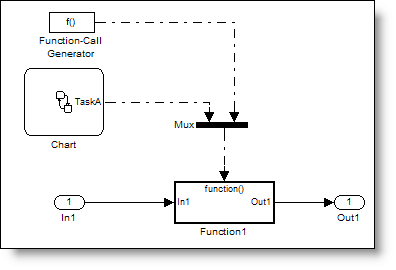
Function calls and Mux Blocks
When you have a single function call initiator, and a single system to be called, the connection is simply from initiator to the system being called. When you have multiple function call initiators, the Mux block is used to join the function calls together. (Blocks can only have one function call port.)
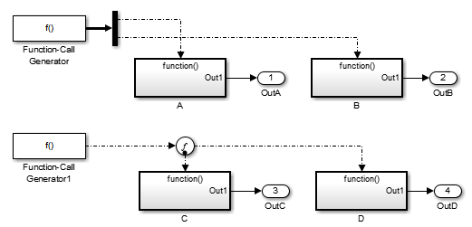
Function calls and Demux Blocks
When a single initiator needs to call multiple systems, the Demux Block allows you to split the signal. This is a very important semantic role for the Demux Block because function call signals are not allowed to branch like normal signals. Function call signals determine the execution order of the blocks they are connected to. If a function call was to branch, which destination system would be executed first? The Demux Block specifies the order of execution based on the port number that the signal is connected to. Port numbers are always counted from top to bottom, or left to right. Here is an example:
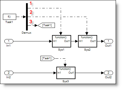
In this example, the function call initiator Task1 will execute Sys1, Sys2 and Sys3 in that order. I don’t know about you, but when I look at that picture I feel an aesthetic desire to uncross the lines going to Sys1 and Sys2. My urge is to reconnect the first and second outport from the Demux in order to uncross the signals, like this:
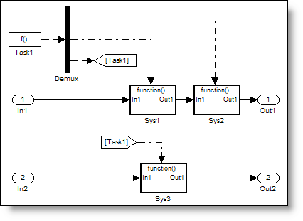
This would fundamentally change the behavior of the system. The order of execution would then be Sys2, Sys1, and then Sys3. The Demux Block is an important part of function call semantics, and semantics trump aesthetics.
What do you think?
You may have started reading this post with the expectation to learn all about Mux and Demux, but you also got my elevator speech about function calls. Did you know about this use for Mux and Demux? What is new or different in your mental model for these blocks? Leave a comment and tell me about it.
- Category:
- Signals


Comments
To leave a comment, please click here to sign in to your MathWorks Account or create a new one.