
Bus Objects and Interface Specifications
A few recent comments on this blog have asked about bus
objects. Blog reader KMR
remarked that "bus objects are one of the most important parts of the
whole bus concept: allowing you to lock down an interface." This week I introduce bus objects
and how they can help avoid modeling errors.
Bus objects provide a specification
In an earlier
post, we saw that virtual bus signals do not have to include any
information about the size and datatype of their signals. This information
propagates from the other blocks (like sources and Inports) in the diagram.
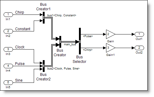
The simplebusdemo.mdl
doesn’t need a specification for the bus signal because it is virtual. Our
mental model of the bus signal is a bundle of rainbow colored wires that link
the sources to their destinations. We often refer to a bus as a tie-wrap of
signals.
 If you did want to lock down the description of this bus,
you must use a bus object. If the bus is the rainbow colored bundle of wires,
in my mental model the bus object is the definition for the cable
connector at the end of that bundle. It defines all the pins and their
exact configuration and asserts that only those types of signals may be
connected.
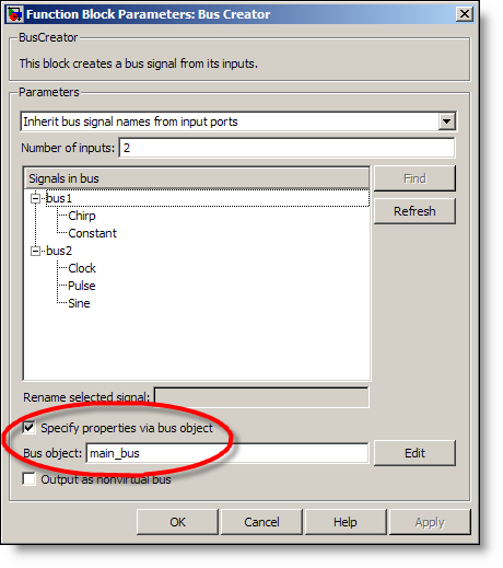
Check “Specify properties via bus object” and include the
bus object name on the Bus Creator blocks to add the specification to your
model. I’ll get to creating bus objects in the next section.
If you did want to lock down the description of this bus,
you must use a bus object. If the bus is the rainbow colored bundle of wires,
in my mental model the bus object is the definition for the cable
connector at the end of that bundle. It defines all the pins and their
exact configuration and asserts that only those types of signals may be
connected.
Check “Specify properties via bus object” and include the
bus object name on the Bus Creator blocks to add the specification to your
model. I’ll get to creating bus objects in the next section.
 Bus Creators use bus objects for error checking. If the
input signals do not have the same types and dimensions as the elements in the
bus object Simulink will error. There is also a connectivity diagnostic to
check for element name mismatch in the bus object. Turn the diagnostic up to
warning or error to ensure your signals are consistent with the block
specification.
Making a bus object
The easiest way to make a bus object is directly from your
diagram. Simulink.Bus.createObject
is a function that generates a bus object for the block you specify based on
your diagram. Specify the bus creator or port that has the highest level in
the hierarchy of the bus. Simulink.Bus.createObject recursively creates bus objects for buses
that feed into the given block. For our example, the main_bus is specified by the
simplebusdemo/Bus Creator (not Bus Creator1 or Bus Creator2).
Bus Creators use bus objects for error checking. If the
input signals do not have the same types and dimensions as the elements in the
bus object Simulink will error. There is also a connectivity diagnostic to
check for element name mismatch in the bus object. Turn the diagnostic up to
warning or error to ensure your signals are consistent with the block
specification.
Making a bus object
The easiest way to make a bus object is directly from your
diagram. Simulink.Bus.createObject
is a function that generates a bus object for the block you specify based on
your diagram. Specify the bus creator or port that has the highest level in
the hierarchy of the bus. Simulink.Bus.createObject recursively creates bus objects for buses
that feed into the given block. For our example, the main_bus is specified by the
simplebusdemo/Bus Creator (not Bus Creator1 or Bus Creator2).
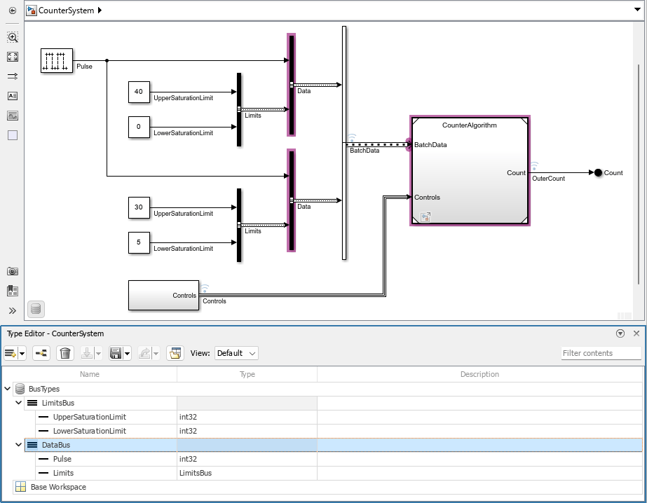
 As of R2008a Simulink has a new bus editor, so unless you
are using this release, your version will look different. The left pane shows
all bus objects in the workspace. The selected node in the tree displays its
children in the center pane, and on the right, you have the details for each
selected element. The information about dimensions, datatype and signal name
are all a part of the bus object. For hierarchical bus signals, the element
datatype is the name of another bus. Looking at the main_bus, it has two
signals, bus1 of type bus1, and bus2 of type bus2. The name and type do not
have to match, but they do in this case.
If you are happy with your bus objects, I recommend saving
them to a MAT-file so you do not have to regenerate them every time. Some
people prefer to generate an M-file and call that as part of their initialization
routines, instead of loading the MAT-file. I have automatically generated this
M-file during the call to Simulink.Bus.createObject. Given an output file
name, Simulink.bus.createObject also outputs the code you need to make that bus
object.
As of R2008a Simulink has a new bus editor, so unless you
are using this release, your version will look different. The left pane shows
all bus objects in the workspace. The selected node in the tree displays its
children in the center pane, and on the right, you have the details for each
selected element. The information about dimensions, datatype and signal name
are all a part of the bus object. For hierarchical bus signals, the element
datatype is the name of another bus. Looking at the main_bus, it has two
signals, bus1 of type bus1, and bus2 of type bus2. The name and type do not
have to match, but they do in this case.
If you are happy with your bus objects, I recommend saving
them to a MAT-file so you do not have to regenerate them every time. Some
people prefer to generate an M-file and call that as part of their initialization
routines, instead of loading the MAT-file. I have automatically generated this
M-file during the call to Simulink.Bus.createObject. Given an output file
name, Simulink.bus.createObject also outputs the code you need to make that bus
object.
 As you can see, the bus object has locked down the
specification for the signals fed into the bus creator. When something does
not match Simulink reports an error.
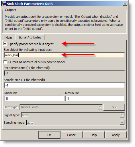
Bus objects can be specified on ports
In addition to the bus creators, Inports and Outports can
also be fully specified with a bus object. When a bus object is used on a port
you are asserting that only that special type of connector can be used with
that port. This port could be a root level Inport or Outport, or a port on a
subsystem. If the subsystem is in a library, you have defined its interface,
and all instances of the library block must match the specification.
As you can see, the bus object has locked down the
specification for the signals fed into the bus creator. When something does
not match Simulink reports an error.
Bus objects can be specified on ports
In addition to the bus creators, Inports and Outports can
also be fully specified with a bus object. When a bus object is used on a port
you are asserting that only that special type of connector can be used with
that port. This port could be a root level Inport or Outport, or a port on a
subsystem. If the subsystem is in a library, you have defined its interface,
and all instances of the library block must match the specification.
 Getting back to the comment that “[bus objects] are one of
the most important parts of the whole bus concept: allowing you to lock down an
interface.” The concept of locking down an interface is important to
developing reusable components as well as working with others on large modeling
projects. This is a very powerful concept I have seen used in conjunction with
an interface control document (ICD) to define the interface to a system. The
document specifies the characteristics of the bus signals, and the bus object
enforces that those characteristics are true.
I have also seen a Simulink model specify the interface, with a script used
to generate the ICD from the model. This makes the Simulink model the single
source of truth. Your model will always be in sync with the specification if
this is your workflow.
Now it’s your turn
What do you think about bus objects? Do you use them? I
still have not had anyone volunteer to show off their use of bus signals with a
screen capture from their model. Leave a comment
and then send
me an e-mail with the image. I will post it for you and we can all marvel
at your work.
Getting back to the comment that “[bus objects] are one of
the most important parts of the whole bus concept: allowing you to lock down an
interface.” The concept of locking down an interface is important to
developing reusable components as well as working with others on large modeling
projects. This is a very powerful concept I have seen used in conjunction with
an interface control document (ICD) to define the interface to a system. The
document specifies the characteristics of the bus signals, and the bus object
enforces that those characteristics are true.
I have also seen a Simulink model specify the interface, with a script used
to generate the ICD from the model. This makes the Simulink model the single
source of truth. Your model will always be in sync with the specification if
this is your workflow.
Now it’s your turn
What do you think about bus objects? Do you use them? I
still have not had anyone volunteer to show off their use of bus signals with a
screen capture from their model. Leave a comment
and then send
me an e-mail with the image. I will post it for you and we can all marvel
at your work.
If you did want to lock down the description of this bus,
you must use a bus object. If the bus is the rainbow colored bundle of wires,
in my mental model the bus object is the definition for the cable
connector at the end of that bundle. It defines all the pins and their
exact configuration and asserts that only those types of signals may be
connected.
Check “Specify properties via bus object” and include the
bus object name on the Bus Creator blocks to add the specification to your
model. I’ll get to creating bus objects in the next section.
Bus Creators use bus objects for error checking. If the
input signals do not have the same types and dimensions as the elements in the
bus object Simulink will error. There is also a connectivity diagnostic to
check for element name mismatch in the bus object. Turn the diagnostic up to
warning or error to ensure your signals are consistent with the block
specification.
Making a bus object
The easiest way to make a bus object is directly from your
diagram. Simulink.Bus.createObject
is a function that generates a bus object for the block you specify based on
your diagram. Specify the bus creator or port that has the highest level in
the hierarchy of the bus. Simulink.Bus.createObject recursively creates bus objects for buses
that feed into the given block. For our example, the main_bus is specified by the
simplebusdemo/Bus Creator (not Bus Creator1 or Bus Creator2).
>> Simulink.Bus.createObject('simplebusdemo', 'simplebusdemo/Bus Creator');
>> whos
Name Size Bytes Class Attributes

ans 1x1 272 struct
bus1 1x1 Simulink.Bus
bus2 1x1 Simulink.Bus
main_bus 1x1 Simulink.Bus
To look at bus objects, use the buseditor. (click to enlarge)
 As of R2008a Simulink has a new bus editor, so unless you
are using this release, your version will look different. The left pane shows
all bus objects in the workspace. The selected node in the tree displays its
children in the center pane, and on the right, you have the details for each
selected element. The information about dimensions, datatype and signal name
are all a part of the bus object. For hierarchical bus signals, the element
datatype is the name of another bus. Looking at the main_bus, it has two
signals, bus1 of type bus1, and bus2 of type bus2. The name and type do not
have to match, but they do in this case.
If you are happy with your bus objects, I recommend saving
them to a MAT-file so you do not have to regenerate them every time. Some
people prefer to generate an M-file and call that as part of their initialization
routines, instead of loading the MAT-file. I have automatically generated this
M-file during the call to Simulink.Bus.createObject. Given an output file
name, Simulink.bus.createObject also outputs the code you need to make that bus
object.
As of R2008a Simulink has a new bus editor, so unless you
are using this release, your version will look different. The left pane shows
all bus objects in the workspace. The selected node in the tree displays its
children in the center pane, and on the right, you have the details for each
selected element. The information about dimensions, datatype and signal name
are all a part of the bus object. For hierarchical bus signals, the element
datatype is the name of another bus. Looking at the main_bus, it has two
signals, bus1 of type bus1, and bus2 of type bus2. The name and type do not
have to match, but they do in this case.
If you are happy with your bus objects, I recommend saving
them to a MAT-file so you do not have to regenerate them every time. Some
people prefer to generate an M-file and call that as part of their initialization
routines, instead of loading the MAT-file. I have automatically generated this
M-file during the call to Simulink.Bus.createObject. Given an output file
name, Simulink.bus.createObject also outputs the code you need to make that bus
object.
>> Simulink.Bus.createObject('simplebusdemo',...
'simplebusdemo/Bus Creator','simplebusdemo_busScript');
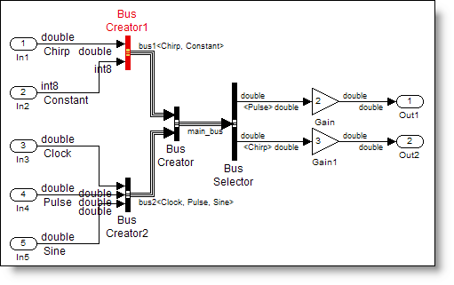
Bus specification in action
If I change my constant input signal to be type int8 instead
of double Simulink will throw an error during update diagram (Ctrl-D).
The input bus to block
'simplebusdemo_bo_error/Bus Creator1' does not match the bus specified by the
bus object 'bus1' on the block dialog. The following errors were detected :
Bus element 'Constant' of bus
object 'bus1' is specified to be of datatype 'double', but the incoming signal
has a datatype of 'int8'.- Category:
- Signals


Comments
To leave a comment, please click here to sign in to your MathWorks Account or create a new one.