Guy and Seth on Simulink
April 17th, 2009
S-functions, Bus Signals, and Missing Documentation
This almost never happens, but today I get to share with you
an undocumented Simulink capability! In R2009a the S-function builder
has the ability to accept bus signals at its input and output ports. We accidentally
omitted the updated doc section when R2009a shipped. You can find the missing
documentation here, but I still want to tell you about how to use bus
signals with S-function Builder.
What is an S-function?
If you want to build your own custom block in Simulink, we
provide a couple ways to do it. For now, I am going to ignoring masked
subsystems and reference models and focus on block authoring in the truest
sense, the S-function. The "S" in S-function stands for System (or
maybe Simulink). S-functions define how a block works during the different
parts of the simulation, for example: initialization, update, derivatives,
outputs, and termination. S-function are often used as a gateway to other
simulation environments, interfaces to hardware or software. There are a few
ways to implement
an S-function, such as using an M-file or a C-MEX file. There are also
tools like the S-function
Builder Block and the Legacy
Code Tool to make it easier to write S-functions.

The S-function must define itself as a system. You have to
define the interfaces and algorithm for the system. The interfaces to the
system are the ports and parameters of the block. For a long time, users have
asked for the ability to write an S-function that accepts a bus signal as the
input, or provides a bus signal as the output. This is the capability added in
R2009a for the S-function Builder.
S-functions and Bus Signals
In January 2005, Tom
Erkkinen posted the Legacy Code Tool (LCT) to the MATLAB Central File
Exchange. The Legacy Code Tool helps you integrate
existing C functions into your Simulink model by generating an S-function.
LCT has been shipping with Simulink since R2006b. One of the major
capabilities of LCT is the ability to interface to bus signals. If your
function requires a structure input or returns a structure output, LCT can
generate the wrapper S-function that handles a bus signal.
S-function Builder Bus Support
I think the S-function Builder block is the easiest way to
bring a short C code algorithm into your Simulink model. New in R2009a, the S-function
Builder block now supports bus signals for the input and output ports. There
is a demo model called sfbuilder_bususage. Here is how it works:
The S-function builder works like many software wizards, and
leads you through the process of writing an S-function. When you double click
on the S-function builder block, you get a GUI that looks like this.

If you start on the left most tab, add information in each
tab, by the time you have reach the last tab, you are done. To include a bus
input in the S-function builder, you need to define a bus object. In a
previous post, I talked about how to do use bus
objects as interface specifications. The Data Properties tab defines all
the information for the ports of the S-function. First, you have to define the
inputs and outputs of your system.

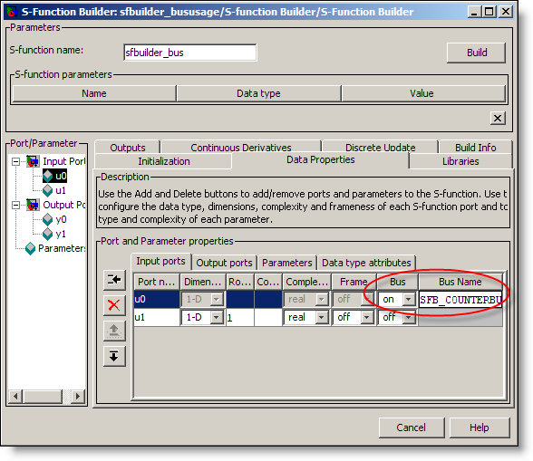
To include a bus, turn the Bus property ON, and se the Bus
Name to the bus object in the base workspace. Next, you have to access
elements of the bus using standard C structure indexing. Here is a snippet
from Outputs function that accesses signals from the bus.

That is all there is to it. The bus object can optionally include
a C header file that defines the C structure definition for the bus. You can
specify this in the Bus Editor:

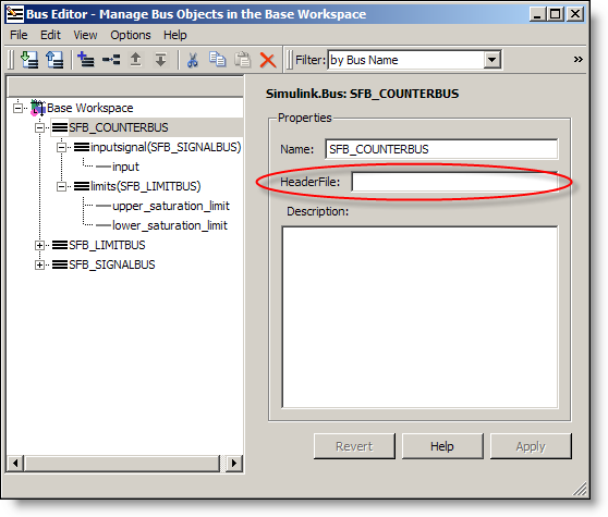
If you include the header file in your bus object, the S-function
builder will use it. If you don’t specify the header file, the S-function
builder will generate one for you that looks like this:

Wait a second, why isn’t this in the doc?
It was just an oversight. There were many changes made to
the doc, and we forgot to include this one. Luckily, when we realized the doc
was not complete, technical support came to the rescue. We have published a
revised section of the S-function builder documentation through a solution
titled:
How can I
input and output Bus signals to and from an S-function created using the
S-function builder in Simulink 7.3 (R2009a)?
Now it’s your turn
Do you write S-functions? Have you tried this feature?
Leave a comment
here and tell me about your experience.
14:05 UTC |
Posted in S-functions, Signals, What's new? |
Permalink |
21 Comments »
You can follow any responses to this entry through the RSS 2.0 feed.
You can skip to the end and leave a response. Pinging is currently not allowed.
Leave a Reply
|
@Seth, If this uses bus object, could Simulink.BusElement be dynamically sized, maybe undocumented?
Seth, I am relative new to Simulink, and only have a Simulink 5/R13 at hand. I know my version does not support bus signal, but is it possible to have some work turnaround for my application: I have to compute a state-space output online based on one of the system state (LPV problem). I’ve written an M file S-function to do the job. However, this varying state signal seems no way for me to get it into the S-function. One approach I tried was to MUX this signal with the inputs, and wanted to separate it from inside the S-function, but did not work. E.g. combine this state signal with two other S-function inputs as a 3-element vector u, and tried to read u(3) as the varying parameter, but always received a “exceeds matrix dimensions” error. Kinda stuck here, and I am not good at C or other complicated programming skills, could you provide some hints or there is another solution without using S-function? Thanks in advance!
@wei – The Simulink.BusElement can not be dynamically sized. As this is a definition for a type, the size must be known. As far as dynamic values for your bus, you can specify Sample Time as -1, and I recommend this.
@Mike – You may need to increase the width of the input to your S-function. If you are using R13, you don’t have access to Level-2 M-file S-functions, so you can’t just add another input port. If you need to input a 3 element vector then:
function [sys,x0,str,ts,simStateCompliance]=mdlInitializeSizes
sizes = simsizes;
sizes.NumContStates = 0;
sizes.NumDiscStates = 0;
sizes.NumOutputs = 0;
sizes.NumInputs = 3; %< ====
sizes.DirFeedthrough = 1;
sizes.NumSampleTimes = 1; % at least one sample time is needed
sys = simsizes(sizes);
@Seth, one can dynamically size inport/outport, but not if signals are grouped as bus. What’s benefit?
@Mike – I would like to suggest another possible solution for your LPV problem: do your computation in blocks! If you look through the Math Operations library you will find things like Product, Gain and Sum blocks. Most people are familiar with working on signals and vectors, but these also work on matrix signals. Try implementing your algorithm using those blocks and avoid building an S-function all together.
@wei – Dynamic sizing only works when the port is virtual and left unspecified (-1). The same is true for Virtual Bus Signals. If a bus signal is left virtual, and you do not specify the bus object, then the behavior is dynamic and calculated during update diagram. When a bus object is present, this provides the definition for the interface. Currently that definition includes information about the number of signals, their size and type. Generally, I suggest leaving bus signals virtual unless you have a reason to specify the interface. The most common example of a non-virtual interface is at Model Reference boundaries. For Model Reference blocks to work, the interface must be fully defined. Do you encounter another situation where you need a non-virtual bus, but you don’t want to specify the size?
@Seth, S-function has dynamically sized port. And number of ports is self-modifiable. It should support virtual bus port.
But now a port has to be non-virtual if it’s a bus. Is the restriction from design that bus object has to be non-virtual? If so, could one define s-function’s bus port by non bus object mean?
Need Help in modeling PWM or SPWM using s-function, it would be great help if modeling of PWM using simulink models available and can be used in s-fucntion modeling.
Thank you
@wei – You have asked a difficult question. S-functions with simple signals (one type and one definition of size) can be dynamically sized, but that was part of the original design for blocks. Bus signals came later, and the purpose of bus objects is to define an interface. Dimensions and data types are the required parts that define that interface. At the boundary, the bus is non-virtual and must be fully defined. I’m not sure I understand your last questions about defining “s-functions bus port by non bus object.” Please clarify if you want more information.
@Gaurav Thaiba – If you are simply looking for a block to output a pulse signal, there are some pulse generators in the Simulink Sources library. You could also model a PWM signal using SimElectronics or SimPowerSystems. Search the documentation for PWM.
Hey Seth,
I have a large struct that I need to pass through a simulink model (presumably by bus object). The struct is created in a Level 2 M-file S-Function. Unfortunately it doesn’t look like Level 2 M-file S-Functions support bus ports, do you have any recommendations for making this work? The struct is way too complicated to multiplex into a single matrix.
Thanks!
Seth,
Just FYI, I found a bug in the S-Function Builder. If you try to create an S-Function with a bus output and no inputs, the builder messes up while generating the code (inserts an extra comma where the input argument usually is) that causes build errors, rendering the builder GUI useless.
Thanks,
Jeff
@Jeff – Regarding your first question about handling a bus with a Level 2 M-file S-function: you are correct, level 2 M-file S-functions do not support bus signals, but there are some other options.
I think the Embedded MATLAB option may be best, though, the Embedded MATLAB language is a subset of what you can do in the M-file S-function. Embedded MATLAB blocks don’t have states the way S-functions do, so you may have to rething your code if you rely on them.
Regarding your second comment about the S-function builder bug, thanks for reporting it. Technical Support is looking into this.
Hi Seth,
Thanks for the feedback. I actually decided to go with the second option since it made more sense for me to have an initialization step and subsequent output steps.
Have you played around with the dynamic port dimensions in the latest prerelease (2009b)? I’m looking at having a bus with elements of varying dimensions, but I haven’t found any documentation on the updates to the bus editor. I take it prereleases don’t come with documentation?
P.S. Glad y’all spotted the bug!
Thanks,
Jeff
Hi, i tried modifying a level 2 s-funtion. however i keep getting an error.
please help. im new to simulink so i almost have no idea.
i am pasting the code here. please advise on what to…
50
d=d-2; %reduce dutycycle by 2
else
d=d+2; %increment dutycycle by 2
end
set_param(block.Dwork(2).Data, ‘PulseWidth’, num2str(d));
%endfunction
function Update(block)
d=50;
% Store the input value in the Dwork(1)
block.Dwork(1).Data = d;
%endfunction
function Terminate(block)
%endfunction
>
sorry about my previous posting. didnt wrap the code properly. here is the full code well wrapped
function msfcn_varpulseizzy(block) % Level-2 M-file S-function to implement a variable pulse width generator % Copyright 1990-2007 The MathWorks, Inc. % This S-function takes a desired pulse width (in percentage % of the period of a Pulse Generator block) and sets the PulseWidth % property in a Pulse Generator block. The result is a variable-width % pulse signal. The S-function assumes the model contains only one Pulse % Generator block and modifies the PulseWidth of that block. setup(block); %endfunction function setup(block) % Register number of ports block.NumDialogPrms = 1; block.NumInputPorts = 1; block.NumOutputPorts = 0; % Setup port properties to be inherited or dynamic block.SetPreCompInpPortInfoToDynamic; block.SetPreCompOutPortInfoToDynamic; % Override input port properties block.InputPort(1).DatatypeID = 0; % double block.InputPort(1).Complexity = 'Real'; % Register sample times block.SampleTimes = [0 0]; % Register methods block.RegBlockMethod('PostPropagationSetup', @DoPostPropSetup); block.RegBlockMethod('InitializeConditions', @InitializeConditions); block.RegBlockMethod('Start', @Start); block.RegBlockMethod('Outputs', @Outputs); block.RegBlockMethod('Update', @Update); block.RegBlockMethod('Terminate', @Terminate); %endfunction function DoPostPropSetup(block) % Initialize the Dwork vector block.NumDworks = 2; % Dwork(1) stores the value of the next pulse width block.Dwork(1).Name = 'x1'; block.Dwork(1).Dimensions = 1; block.Dwork(1).DatatypeID = 0; % double block.Dwork(1).Complexity = 'Real'; % real block.Dwork(1).UsedAsDiscState = true; % Dwork(2) stores the handle of the Pulse Geneator block block.Dwork(2).Name = 'BlockHandle'; block.Dwork(2).Dimensions = 1; block.Dwork(2).DatatypeID = 0; % double block.Dwork(2).Complexity = 'Real'; % real block.Dwork(2).UsedAsDiscState = false; %endfunction function Start(block) % Populate the Dwork vector block.Dwork(1).Data = 0; % Obtain the Pulse Generator block handle pulseGen = find_system(gcs,'BlockType','DiscretePulseGenerator'); blockH = get_param(pulseGen{1},'Handle'); block.Dwork(2).Data = blockH; %endfunction function InitializeConditions(block) % Set the initial pulse width value d=50; set_param(block.Dwork(2).Data, 'PulseWidth', num2str(d)); %endfunction function Outputs(block) % Update the pulse width value if block.InputPort(1).Data>50 d=d-2; %reduce dutycycle by 2 else d=d+2; %increment dutycycle by 2 end set_param(block.Dwork(2).Data, 'PulseWidth', num2str(d)); %endfunction function Update(block) d=50; % Store the input value in the Dwork(1) block.Dwork(1).Data = d; %endfunction function Terminate(block) %endfunction@Seth–nice post on Bus
I am having a problem with Bus and embedded Maltab, I need non virtual bus as I a defining interfaces. I have replicated the example of the online Documentation->Simulink->Using the embedded Matlab Function Blocks–> Working with structures and Bus signals.
It just does not work and I am wondering what the problem might be, This is an excerpt of message I am getting from Matlab,
Warning: ‘testDescription/Bus Selector2′ must be connected to a Bus Creator, Bus
Selector or a bus capable block.
A possible cause of this error is the use of a bus-capable block (such as Merge or
Unit Delay) that in this current situation is unable to propagate the bus
downstream to the block reported in this error. Please see Simulink documentation
for further information on composite (i.e. bus) signals and their proper usage.
> In busSelectorddg_cb at 37
In busSelectorddg_cb at 111
“
As I cant attached my model file, please accept my apology for adding the content of my mdl file here.
/**************************************************/
Model {
Name “testDescription”
Version 7.3
MdlSubVersion 0
GraphicalInterface {
NumRootInports 0
NumRootOutports 0
ParameterArgumentNames “”
ComputedModelVersion “1.87″
NumModelReferences 0
NumTestPointedSignals 0
}
SavedCharacterEncoding “ibm-5348_P100-1997″
SaveDefaultBlockParams on
ScopeRefreshTime 0.035000
OverrideScopeRefreshTime on
DisableAllScopes off
DataTypeOverride “UseLocalSettings”
MinMaxOverflowLogging “UseLocalSettings”
MinMaxOverflowArchiveMode “Overwrite”
Created “Sat Jul 04 08:00:35 2009″
Creator “Admin”
UpdateHistory “UpdateHistoryNever”
ModifiedByFormat “%”
LastModifiedBy “Admin”
ModifiedDateFormat “%”
LastModifiedDate “Mon Jul 06 22:54:24 2009″
RTWModifiedTimeStamp 0
ModelVersionFormat “1.%”
ConfigurationManager “None”
SampleTimeColors on
SampleTimeAnnotations off
LibraryLinkDisplay “none”
WideLines on
ShowLineDimensions on
ShowPortDataTypes on
ShowLoopsOnError on
IgnoreBidirectionalLines off
ShowStorageClass on
ShowTestPointIcons on
ShowSignalResolutionIcons on
ShowViewerIcons on
SortedOrder off
ExecutionContextIcon off
ShowLinearizationAnnotations on
BlockNameDataTip off
BlockParametersDataTip off
BlockDescriptionStringDataTip off
ToolBar on
StatusBar on
BrowserShowLibraryLinks off
BrowserLookUnderMasks off
SimulationMode “normal”
LinearizationMsg “none”
Profile off
ParamWorkspaceSource “MATLABWorkspace”
AccelSystemTargetFile “accel.tlc”
AccelTemplateMakefile “accel_default_tmf”
AccelMakeCommand “make_rtw”
TryForcingSFcnDF off
RecordCoverage off
CovPath “/”
CovSaveName “covdata”
CovMetricSettings “dw”
CovNameIncrementing off
CovHtmlReporting on
covSaveCumulativeToWorkspaceVar on
CovSaveSingleToWorkspaceVar on
CovCumulativeVarName “covCumulativeData”
CovCumulativeReport off
CovReportOnPause on
CovModelRefEnable “Off”
CovExternalEMLEnable off
ExtModeBatchMode off
ExtModeEnableFloating on
ExtModeTrigType “manual”
ExtModeTrigMode “normal”
ExtModeTrigPort “1″
ExtModeTrigElement “any”
ExtModeTrigDuration 1000
ExtModeTrigDurationFloating “auto”
ExtModeTrigHoldOff 0
ExtModeTrigDelay 0
ExtModeTrigDirection “rising”
ExtModeTrigLevel 0
ExtModeArchiveMode “off”
ExtModeAutoIncOneShot off
ExtModeIncDirWhenArm off
ExtModeAddSuffixToVar off
ExtModeWriteAllDataToWs off
ExtModeArmWhenConnect on
ExtModeSkipDownloadWhenConnect off
ExtModeLogAll on
ExtModeAutoUpdateStatusClock on
BufferReuse off
ShowModelReferenceBlockVersion off
ShowModelReferenceBlockIO off
Array {
Type “Handle”
Dimension 1
Simulink.ConfigSet {
$ObjectID 1
Version “1.6.0″
Array {
Type “Handle”
Dimension 8
Simulink.SolverCC {
$ObjectID 2
Version “1.6.0″
StartTime “0.0″
StopTime “10.0″
AbsTol “auto”
FixedStep “0.1″
InitialStep “auto”
MaxNumMinSteps “-1″
MaxOrder 5
ZcThreshold “auto”
ConsecutiveZCsStepRelTol “10*128*eps”
MaxConsecutiveZCs “1000″
ExtrapolationOrder 4
NumberNewtonIterations 1
MaxStep “auto”
MinStep “auto”
MaxConsecutiveMinStep “1″
RelTol “1e-3″
SolverMode “Auto”
Solver “FixedStepDiscrete”
SolverName “FixedStepDiscrete”
ShapePreserveControl “DisableAll”
ZeroCrossControl “UseLocalSettings”
ZeroCrossAlgorithm “Nonadaptive”
AlgebraicLoopSolver “TrustRegion”
SolverResetMethod “Fast”
PositivePriorityOrder off
AutoInsertRateTranBlk off
SampleTimeConstraint “Unconstrained”
InsertRTBMode “Whenever possible”
SignalSizeVariationType “Allow only fixed size”
}
Simulink.DataIOCC {
$ObjectID 3
Version “1.6.0″
Decimation “1″
ExternalInput “[t, u]“
FinalStateName “xFinal”
InitialState “xInitial”
LimitDataPoints on
MaxDataPoints “1000″
LoadExternalInput off
LoadInitialState off
SaveFinalState off
SaveCompleteFinalSimState off
SaveFormat “Array”
SaveOutput on
SaveState off
SignalLogging on
InspectSignalLogs off
SaveTime on
StateSaveName “xout”
TimeSaveName “tout”
OutputSaveName “yout”
SignalLoggingName “logsout”
OutputOption “RefineOutputTimes”
OutputTimes “[]“
Refine “1″
}
Simulink.OptimizationCC {
$ObjectID 4
Version “1.6.0″
Array {
Type “Cell”
Dimension 4
Cell “ZeroExternalMemoryAtStartup”
Cell “ZeroInternalMemoryAtStartup”
Cell “NoFixptDivByZeroProtection”
Cell “OptimizeModelRefInitCode”
PropName “DisabledProps”
}
BlockReduction off
BooleanDataType on
ConditionallyExecuteInputs on
InlineParams off
InlineInvariantSignals on
OptimizeBlockIOStorage off
BufferReuse off
EnhancedBackFolding off
StrengthReduction off
EnforceIntegerDowncast on
ExpressionFolding off
EnableMemcpy on
MemcpyThreshold 64
PassReuseOutputArgsAs “Structure reference”
ExpressionDepthLimit 2147483647
FoldNonRolledExpr on
LocalBlockOutputs off
RollThreshold 5
SystemCodeInlineAuto off
StateBitsets off
DataBitsets off
UseTempVars off
ZeroExternalMemoryAtStartup on
ZeroInternalMemoryAtStartup on
InitFltsAndDblsToZero on
NoFixptDivByZeroProtection off
EfficientFloat2IntCast off
EfficientMapNaN2IntZero on
OptimizeModelRefInitCode off
LifeSpan “inf”
BufferReusableBoundary on
SimCompilerOptimization “Off”
AccelVerboseBuild off
}
Simulink.DebuggingCC {
$ObjectID 5
Version “1.6.0″
RTPrefix “error”
ConsistencyChecking “none”
ArrayBoundsChecking “none”
SignalInfNanChecking “none”
SignalRangeChecking “none”
ReadBeforeWriteMsg “UseLocalSettings”
WriteAfterWriteMsg “UseLocalSettings”
WriteAfterReadMsg “UseLocalSettings”
AlgebraicLoopMsg “warning”
ArtificialAlgebraicLoopMsg “warning”
SaveWithDisabledLinksMsg “warning”
SaveWithParameterizedLinksMsg “none”
CheckSSInitialOutputMsg on
UnderspecifiedInitializationDetection “Classic”
MergeDetectMultiDrivingBlocksExec “none”
CheckExecutionContextPreStartOutputMsg off
CheckExecutionContextRuntimeOutputMsg off
SignalResolutionControl “TryResolveAllWithWarning”
BlockPriorityViolationMsg “warning”
MinStepSizeMsg “warning”
TimeAdjustmentMsg “none”
MaxConsecutiveZCsMsg “error”
SolverPrmCheckMsg “warning”
InheritedTsInSrcMsg “warning”
DiscreteInheritContinuousMsg “warning”
MultiTaskDSMMsg “warning”
MultiTaskCondExecSysMsg “none”
MultiTaskRateTransMsg “error”
SingleTaskRateTransMsg “none”
TasksWithSamePriorityMsg “warning”
SigSpecEnsureSampleTimeMsg “warning”
CheckMatrixSingularityMsg “none”
IntegerOverflowMsg “warning”
Int32ToFloatConvMsg “warning”
ParameterDowncastMsg “error”
ParameterOverflowMsg “error”
ParameterUnderflowMsg “none”
ParameterPrecisionLossMsg “warning”
ParameterTunabilityLossMsg “warning”
UnderSpecifiedDataTypeMsg “none”
UnnecessaryDatatypeConvMsg “none”
VectorMatrixConversionMsg “none”
InvalidFcnCallConnMsg “error”
FcnCallInpInsideContextMsg “Use local settings”
SignalLabelMismatchMsg “none”
UnconnectedInputMsg “warning”
UnconnectedOutputMsg “warning”
UnconnectedLineMsg “warning”
SFcnCompatibilityMsg “none”
UniqueDataStoreMsg “none”
BusObjectLabelMismatch “warning”
RootOutportRequireBusObject “warning”
AssertControl “UseLocalSettings”
EnableOverflowDetection off
ModelReferenceIOMsg “none”
ModelReferenceVersionMismatchMessage “none”
ModelReferenceIOMismatchMessage “none”
ModelReferenceCSMismatchMessage “none”
UnknownTsInhSupMsg “warning”
ModelReferenceDataLoggingMessage “warning”
ModelReferenceSymbolNameMessage “warning”
ModelReferenceExtraNoncontSigs “error”
StateNameClashWarn “warning”
StrictBusMsg “ErrorOnBusTreatedAsVector”
LoggingUnavailableSignals “error”
BlockIODiagnostic “none”
}
Simulink.HardwareCC {
$ObjectID 6
Version “1.6.0″
ProdBitPerChar 8
ProdBitPerShort 16
ProdBitPerInt 32
ProdBitPerLong 32
ProdIntDivRoundTo “Undefined”
ProdEndianess “Unspecified”
ProdWordSize 32
ProdShiftRightIntArith on
ProdHWDeviceType “32-bit Generic”
TargetBitPerChar 8
TargetBitPerShort 16
TargetBitPerInt 32
TargetBitPerLong 32
TargetShiftRightIntArith on
TargetIntDivRoundTo “Undefined”
TargetEndianess “Unspecified”
TargetWordSize 32
TargetTypeEmulationWarnSuppressLevel 0
TargetPreprocMaxBitsSint 32
TargetPreprocMaxBitsUint 32
TargetHWDeviceType “Specified”
TargetUnknown off
ProdEqTarget on
}
Simulink.ModelReferenceCC {
$ObjectID 7
Version “1.6.0″
UpdateModelReferenceTargets “IfOutOfDateOrStructuralChange”
CheckModelReferenceTargetMessage “error”
ModelReferenceNumInstancesAllowed “Multi”
ModelReferencePassRootInputsByReference on
ModelReferenceMinAlgLoopOccurrences off
}
Simulink.SFSimCC {
$ObjectID 8
Version “1.6.0″
SFSimEnableDebug on
SFSimOverflowDetection on
SFSimEcho on
SimBlas on
SimUseLocalCustomCode off
SimBuildMode “sf_incremental_build”
}
Simulink.RTWCC {
$BackupClass “Simulink.RTWCC”
$ObjectID 9
Version “1.6.0″
Array {
Type “Cell”
Dimension 1
Cell “IncludeHyperlinkInReport”
PropName “DisabledProps”
}
SystemTargetFile “grt.tlc”
GenCodeOnly off
MakeCommand “make_rtw”
GenerateMakefile on
TemplateMakefile “grt_default_tmf”
GenerateReport off
SaveLog off
RTWVerbose on
RetainRTWFile off
ProfileTLC off
TLCDebug off
TLCCoverage off
TLCAssert off
ProcessScriptMode “Default”
ConfigurationMode “Optimized”
ConfigAtBuild off
RTWUseLocalCustomCode off
RTWUseSimCustomCode off
IncludeHyperlinkInReport off
LaunchReport off
TargetLang “C”
IncludeBusHierarchyInRTWFileBlockHierarchyMap off
IncludeERTFirstTime on
GenerateTraceInfo off
GenerateTraceReport off
GenerateTraceReportSl off
GenerateTraceReportSf off
GenerateTraceReportEml off
GenerateCodeInfo off
RTWCompilerOptimization “Off”
CheckMdlBeforeBuild “Off”
Array {
Type “Handle”
Dimension 2
Simulink.CodeAppCC {
$ObjectID 10
Version “1.6.0″
Array {
Type “Cell”
Dimension 9
Cell “IgnoreCustomStorageClasses”
Cell “InsertBlockDesc”
Cell “SFDataObjDesc”
Cell “SimulinkDataObjDesc”
Cell “DefineNamingRule”
Cell “SignalNamingRule”
Cell “ParamNamingRule”
Cell “InlinedPrmAccess”
Cell “CustomSymbolStr”
PropName “DisabledProps”
}
ForceParamTrailComments off
GenerateComments on
IgnoreCustomStorageClasses on
IgnoreTestpoints off
IncHierarchyInIds off
MaxIdLength 31
PreserveName off
PreserveNameWithParent off
ShowEliminatedStatement off
IncAutoGenComments off
SimulinkDataObjDesc off
SFDataObjDesc off
IncDataTypeInIds off
MangleLength 1
CustomSymbolStrGlobalVar “$R$N$M”
CustomSymbolStrType “$N$R$M”
CustomSymbolStrField “$N$M”
CustomSymbolStrFcn “$R$N$M$F”
CustomSymbolStrBlkIO “rtb_$N$M”
CustomSymbolStrTmpVar “$N$M”
CustomSymbolStrMacro “$R$N$M”
DefineNamingRule “None”
ParamNamingRule “None”
SignalNamingRule “None”
InsertBlockDesc off
SimulinkBlockComments on
EnableCustomComments off
InlinedPrmAccess “Literals”
ReqsInCode off
UseSimReservedNames off
}
Simulink.GRTTargetCC {
$BackupClass “Simulink.TargetCC”
$ObjectID 11
Version “1.6.0″
Array {
Type “Cell”
Dimension 12
Cell “IncludeMdlTerminateFcn”
Cell “CombineOutputUpdateFcns”
Cell “SuppressErrorStatus”
Cell “ERTCustomFileBanners”
Cell “GenerateSampleERTMain”
Cell “MultiInstanceERTCode”
Cell “PurelyIntegerCode”
Cell “SupportNonFinite”
Cell “SupportComplex”
Cell “SupportAbsoluteTime”
Cell “SupportContinuousTime”
Cell “SupportNonInlinedSFcns”
PropName “DisabledProps”
}
TargetFcnLib “ansi_tfl_tmw.mat”
TargetLibSuffix “”
TargetPreCompLibLocation “”
TargetFunctionLibrary “ANSI_C”
UtilityFuncGeneration “Auto”
ERTMultiwordTypeDef “System defined”
ERTMultiwordLength 256
MultiwordLength 2048
GenerateFullHeader on
GenerateSampleERTMain off
GenerateTestInterfaces off
IsPILTarget off
ModelReferenceCompliant on
ParMdlRefBuildCompliant on
CompOptLevelCompliant on
IncludeMdlTerminateFcn on
CombineOutputUpdateFcns off
SuppressErrorStatus off
ERTFirstTimeCompliant off
IncludeFileDelimiter “Auto”
ERTCustomFileBanners off
SupportAbsoluteTime on
LogVarNameModifier “rt_”
MatFileLogging on
MultiInstanceERTCode off
SupportNonFinite on
SupportComplex on
PurelyIntegerCode off
SupportContinuousTime on
SupportNonInlinedSFcns on
EnableShiftOperators on
ParenthesesLevel “Nominal”
PortableWordSizes off
ModelStepFunctionPrototypeControlCompliant off
CPPClassGenCompliant off
AutosarCompliant off
UseMalloc off
ExtMode off
ExtModeStaticAlloc off
ExtModeTesting off
ExtModeStaticAllocSize 1000000
ExtModeTransport 0
ExtModeMexFile “ext_comm”
ExtModeIntrfLevel “Level1″
RTWCAPISignals off
RTWCAPIParams off
RTWCAPIStates off
GenerateASAP2 off
}
PropName “Components”
}
}
PropName “Components”
}
Name “Configuration”
CurrentDlgPage “Optimization”
ConfigPrmDlgPosition ” [ 200, 85, 1080, 715 ] “
}
PropName “ConfigurationSets”
}
Simulink.ConfigSet {
$PropName “ActiveConfigurationSet”
$ObjectID 1
}
BlockDefaults {
ForegroundColor “black”
BackgroundColor “white”
DropShadow off
NamePlacement “normal”
FontName “Helvetica”
FontSize 10
FontWeight “normal”
FontAngle “normal”
ShowName on
BlockRotation 0
BlockMirror off
}
AnnotationDefaults {
HorizontalAlignment “center”
VerticalAlignment “middle”
ForegroundColor “black”
BackgroundColor “white”
DropShadow off
FontName “Helvetica”
FontSize 10
FontWeight “normal”
FontAngle “normal”
UseDisplayTextAsClickCallback off
}
LineDefaults {
FontName “Helvetica”
FontSize 9
FontWeight “normal”
FontAngle “normal”
}
BlockParameterDefaults {
Block {
BlockType BusCreator
Inputs “4″
DisplayOption “none”
UseBusObject off
BusObject “BusObject”
NonVirtualBus off
}
Block {
BlockType BusSelector
OutputAsBus off
}
Block {
BlockType Constant
Value “1″
VectorParams1D on
SamplingMode “Sample based”
OutMin “[]“
OutMax “[]“
OutDataTypeMode “Inherit from ‘Constant value’”
OutDataType “fixdt(1,16,0)”
ConRadixGroup “Use specified scaling”
OutScaling “[]“
OutDataTypeStr “Inherit: Inherit from ‘Constant value’”
LockScale off
SampleTime “inf”
FramePeriod “inf”
}
Block {
BlockType Demux
Outputs “4″
DisplayOption “none”
BusSelectionMode off
}
Block {
BlockType Display
Format “short”
Decimation “10″
Floating off
SampleTime “-1″
}
Block {
BlockType Inport
Port “1″
UseBusObject off
BusObject “BusObject”
BusOutputAsStruct off
PortDimensions “-1″
SampleTime “-1″
OutMin “[]“
OutMax “[]“
DataType “auto”
OutDataType “fixdt(1,16,0)”
OutScaling “[]“
OutDataTypeStr “Inherit: auto”
LockScale off
SignalType “auto”
SamplingMode “auto”
LatchByDelayingOutsideSignal off
LatchByCopyingInsideSignal off
Interpolate on
DimensionsMode “auto”
}
Block {
BlockType Outport
Port “1″
UseBusObject off
BusObject “BusObject”
BusOutputAsStruct off
PortDimensions “-1″
SampleTime “-1″
OutMin “[]“
OutMax “[]“
DataType “auto”
OutDataType “fixdt(1,16,0)”
OutScaling “[]“
OutDataTypeStr “Inherit: auto”
LockScale off
SignalType “auto”
SamplingMode “auto”
SourceOfInitialOutputValue “Dialog”
OutputWhenDisabled “held”
InitialOutput “[]“
DimensionsMode “auto”
}
Block {
BlockType “S-Function”
FunctionName “system”
SFunctionModules “””
PortCounts “[]“
SFunctionDeploymentMode off
}
Block {
BlockType SubSystem
ShowPortLabels “FromPortIcon”
Permissions “ReadWrite”
PermitHierarchicalResolution “All”
TreatAsAtomicUnit off
CheckFcnCallInpInsideContextMsg off
SystemSampleTime “-1″
RTWFcnNameOpts “Auto”
RTWFileNameOpts “Auto”
RTWMemSecFuncInitTerm “Inherit from model”
RTWMemSecFuncExecute “Inherit from model”
RTWMemSecDataConstants “Inherit from model”
RTWMemSecDataInternal “Inherit from model”
RTWMemSecDataParameters “Inherit from model”
SimViewingDevice off
DataTypeOverride “UseLocalSettings”
MinMaxOverflowLogging “UseLocalSettings”
}
Block {
BlockType Terminator
}
}
System {
Name “testDescription”
Location [317, 358, 1148, 746]
Open on
ModelBrowserVisibility off
ModelBrowserWidth 200
ScreenColor “white”
PaperOrientation “landscape”
PaperPositionMode “auto”
PaperType “A4″
PaperUnits “centimeters”
TiledPaperMargins [1.270000, 1.270000, 1.270000, 1.270000]
TiledPageScale 1
ShowPageBoundaries off
ZoomFactor “100″
ReportName “simulink-default.rpt”
Block {
BlockType BusCreator
Name “Bus\nCreator”
Ports [3, 1]
Position [220, 55, 225, 135]
ShowName off
Inputs “3″
DisplayOption “bar”
UseBusObject on
BusObject “MainBus”
NonVirtualBus on
Port {
PortNumber 1
PropagatedSignals “ele1, ele2, a1, a2″
ShowPropagatedSignals “all”
RTWStorageClass “Auto”
DataLoggingNameMode “SignalName”
}
}
Block {
BlockType BusCreator
Name “Bus\nCreator1″
Ports [2, 1]
Position [175, 186, 180, 224]
ShowName off
Inputs “2″
DisplayOption “bar”
UseBusObject on
BusObject “SubBus”
NonVirtualBus on
Port {
PortNumber 1
Name “ele3″
PropagatedSignals “a1, a2″
ShowPropagatedSignals “on”
RTWStorageClass “Auto”
DataLoggingNameMode “SignalName”
}
}
Block {
BlockType BusSelector
Name “Bus\nSelector1″
Ports [1, 2]
Position [620, 56, 625, 94]
ShowName off
OutputSignals “signal1,signal2″
Port {
PortNumber 1
Name “”
RTWStorageClass “Auto”
DataLoggingNameMode “SignalName”
}
Port {
PortNumber 2
Name “”
RTWStorageClass “Auto”
DataLoggingNameMode “SignalName”
}
}
Block {
BlockType BusSelector
Name “Bus\nSelector2″
Ports [1, 2]
Position [590, 221, 595, 259]
ShowName off
OutputSignals “signal1,signal2″
Port {
PortNumber 1
Name “”
RTWStorageClass “Auto”
DataLoggingNameMode “SignalName”
}
Port {
PortNumber 2
Name “”
RTWStorageClass “Auto”
DataLoggingNameMode “SignalName”
}
}
Block {
BlockType Constant
Name “Constant”
Position [95, 25, 125, 55]
Value “100″
OutDataTypeMode “double”
OutDataType “sfix(16)”
OutScaling “2^0″
OutDataTypeStr “double”
Port {
PortNumber 1
Name “ele1″
RTWStorageClass “Auto”
DataLoggingNameMode “SignalName”
}
}
Block {
BlockType Constant
Name “Constant1″
Position [95, 85, 125, 115]
Value “21″
OutDataTypeMode “single”
OutDataType “sfix(16)”
OutScaling “2^0″
OutDataTypeStr “single”
Port {
PortNumber 1
Name “ele2″
RTWStorageClass “Auto”
DataLoggingNameMode “SignalName”
}
}
Block {
BlockType Constant
Name “Constant2″
Position [90, 165, 120, 195]
Value “12″
OutDataTypeMode “double”
OutDataType “sfix(16)”
OutScaling “2^0″
OutDataTypeStr “double”
Port {
PortNumber 1
Name “a1″
RTWStorageClass “Auto”
DataLoggingNameMode “SignalName”
}
}
Block {
BlockType Constant
Name “Constant3″
Position [95, 240, 125, 270]
Value “13″
OutDataTypeMode “double”
OutDataType “sfix(16)”
OutScaling “2^0″
OutDataTypeStr “double”
Port {
PortNumber 1
Name “a2″
RTWStorageClass “Auto”
DataLoggingNameMode “SignalName”
}
}
Block {
BlockType Display
Name “Display”
Ports [1]
Position [715, 30, 805, 60]
Decimation “1″
Lockdown off
}
Block {
BlockType Display
Name “Display1″
Ports [1]
Position [715, 75, 805, 105]
Decimation “1″
Lockdown off
}
Block {
BlockType Display
Name “Display2″
Ports [1]
Position [715, 125, 805, 155]
Decimation “1″
Lockdown off
}
Block {
BlockType Display
Name “Display3″
Ports [1]
Position [715, 170, 805, 200]
Decimation “1″
Lockdown off
}
Block {
BlockType Display
Name “Display4″
Ports [1]
Position [720, 225, 810, 255]
Decimation “1″
Lockdown off
}
Block {
BlockType Display
Name “Display5″
Ports [1]
Position [720, 270, 810, 300]
Decimation “1″
Lockdown off
}
Block {
BlockType SubSystem
Name “Embedded\nMATLAB Function\n–COMPUTATION UNIT–”
Ports [1, 2]
Position [365, 90, 520, 190]
PermitHierarchicalResolution “ExplicitOnly”
MinAlgLoopOccurrences off
PropExecContextOutsideSubsystem off
RTWSystemCode “Auto”
FunctionWithSeparateData off
Opaque off
RequestExecContextInheritance off
MaskHideContents off
MaskType “Stateflow”
MaskDescription “Embedded MATLAB block”
MaskDisplay “disp(‘cityBankBranch’);”
MaskSelfModifiable on
MaskIconFrame on
MaskIconOpaque off
MaskIconRotate “none”
MaskPortRotate “default”
MaskIconUnits “autoscale”
Port {
PortNumber 1
ShowPropagatedSignals “on”
RTWStorageClass “Auto”
DataLoggingNameMode “SignalName”
}
Port {
PortNumber 2
ShowPropagatedSignals “on”
RTWStorageClass “Auto”
DataLoggingNameMode “SignalName”
}
System {
Name “Embedded\nMATLAB Function\n–COMPUTATION UNIT–”
Location [257, 457, 812, 717]
Open off
ModelBrowserVisibility off
ModelBrowserWidth 200
ScreenColor “white”
PaperOrientation “landscape”
PaperPositionMode “auto”
PaperType “A4″
PaperUnits “centimeters”
TiledPaperMargins [1.270000, 1.270000, 1.270000, 1.270000]
TiledPageScale 1
ShowPageBoundaries off
ZoomFactor “100″
Block {
BlockType Inport
Name “inbus”
Position [20, 101, 40, 119]
IconDisplay “Port number”
OutDataType “sfix(16)”
OutScaling “2^0″
}
Block {
BlockType Demux
Name ” Demux “
Ports [1, 1]
Position [270, 180, 320, 220]
Outputs “1″
}
Block {
BlockType “S-Function”
Name ” SFunction “
Tag “Stateflow S-Function testDescription 1″
Ports [1, 3]
Position [180, 100, 230, 180]
FunctionName “sf_sfun”
PortCounts “[1 3]“
EnableBusSupport on
Port {
PortNumber 2
Name “outbus”
RTWStorageClass “Auto”
DataLoggingNameMode “SignalName”
}
Port {
PortNumber 3
Name “outbus1″
RTWStorageClass “Auto”
DataLoggingNameMode “SignalName”
}
}
Block {
BlockType Terminator
Name ” Terminator “
Position [460, 191, 480, 209]
}
Block {
BlockType Outport
Name “outbus”
Position [460, 101, 480, 119]
IconDisplay “Port number”
OutDataType “sfix(16)”
OutScaling “2^0″
}
Block {
BlockType Outport
Name “outbus1″
Position [460, 136, 480, 154]
Port “2″
IconDisplay “Port number”
OutDataType “sfix(16)”
OutScaling “2^0″
}
Line {
SrcBlock ” SFunction “
SrcPort 1
DstBlock ” Demux “
DstPort 1
}
Line {
SrcBlock “inbus”
SrcPort 1
DstBlock ” SFunction “
DstPort 1
}
Line {
Name “outbus”
Labels [0, 0]
SrcBlock ” SFunction “
SrcPort 2
DstBlock “outbus”
DstPort 1
}
Line {
Name “outbus1″
Labels [0, 0]
SrcBlock ” SFunction “
SrcPort 3
DstBlock “outbus1″
DstPort 1
}
Line {
SrcBlock ” Demux “
SrcPort 1
DstBlock ” Terminator “
DstPort 1
}
}
}
Line {
Name “ele1″
Labels [0, 0]
SrcBlock “Constant”
SrcPort 1
Points [35, 0; 0, 30]
DstBlock “Bus\nCreator”
DstPort 1
}
Line {
Name “ele2″
Labels [0, 0]
SrcBlock “Constant1″
SrcPort 1
Points [75, 0]
DstBlock “Bus\nCreator”
DstPort 2
}
Line {
Name “a1″
Labels [0, 0]
SrcBlock “Constant2″
SrcPort 1
Points [15, 0; 0, 15]
DstBlock “Bus\nCreator1″
DstPort 1
}
Line {
Name “a2″
Labels [0, 0]
SrcBlock “Constant3″
SrcPort 1
Points [15, 0; 0, -40]
DstBlock “Bus\nCreator1″
DstPort 2
}
Line {
Name “ele3″
Labels [0, 0]
SrcBlock “Bus\nCreator1″
SrcPort 1
Points [10, 0; 0, -85]
DstBlock “Bus\nCreator”
DstPort 3
}
Line {
Labels [2, 0]
SrcBlock “Bus\nCreator”
SrcPort 1
Points [45, 0; 0, 45]
DstBlock “Embedded\nMATLAB Function\n–COMPUTATION UNIT–”
DstPort 1
}
Line {
Name “”
Labels [3, 0]
SrcBlock “Bus\nSelector2″
SrcPort 1
Points [50, 0; 0, 10]
DstBlock “Display4″
DstPort 1
}
Line {
Name “”
Labels [0, 0]
SrcBlock “Bus\nSelector2″
SrcPort 2
Points [50, 0; 0, 35]
DstBlock “Display5″
DstPort 1
}
Line {
Labels [0, 0]
SrcBlock “Embedded\nMATLAB Function\n–COMPUTATION UNIT–”
SrcPort 2
Points [10, 0; 0, 75]
DstBlock “Bus\nSelector2″
DstPort 1
}
Line {
Labels [0, 0]
SrcBlock “Embedded\nMATLAB Function\n–COMPUTATION UNIT–”
SrcPort 1
Points [5, 0; 0, -40]
DstBlock “Bus\nSelector1″
DstPort 1
}
Annotation {
Name “MainBus”
Position [229, 149]
}
Annotation {
Name “SubBus”
Position [181, 237]
}
}
}
# Finite State Machines
#
# Stateflow Version 7.1 (R2009a) dated Jan 28 2009, 05:16:58
#
#
Stateflow {
machine {
id 1
name “testDescription”
created “04-Jul-2009 08:00:42″
isLibrary 0
firstTarget 10
sfVersion 71014000.000008
}
chart {
id 2
name “Embedded\nMATLAB Function\n–COMPUTATION UNIT–”
windowPosition [311.813 325.875 200.25 189.75]
viewLimits [0 156.75 0 153.75]
screen [1 1 1280 800 1.333333333333333]
treeNode [0 3 0 0]
firstTransition 5
firstJunction 4
viewObj 2
machine 1
ssIdHighWaterMark 6
decomposition CLUSTER_CHART
type EML_CHART
firstData 6
chartFileNumber 1
disableImplicitCasting 1
eml {
name “cityBankBranch”
}
}
state {
id 3
labelString “eML_blk_kernel()”
position [18 64.5 118 66]
fontSize 12
chart 2
treeNode [2 0 0 0]
superState SUBCHART
subviewer 2
ssIdNumber 1
type FUNC_STATE
decomposition CLUSTER_STATE
eml {
isEML 1
script “function [outbus, outbus1] = cityBankBranch(inbus)\n%substruct.a1 = inbus.ele3.a1;\n%substruct.a2″
” = int8([1 2; 3 4]);\n%substruct.a2 = 4;\nsubstruct = struct(‘a1′,inbus.ele3.a1,’a2′,4);\nmystruct = struct(‘ele”
“1′,20.5,’ele2′,single(100),’ele3′,substruct);\n\noutbus = mystruct;\noutbus.ele3.a2 = 2*(substruct.a2);\n\noutbu”
“s1 = inbus.ele3;\n\n\n% function s = cityBankBranch(descriptionFlag)\n% \n% s.nberOfMethod = 3;\n% s.m”
“ethod(1).name = ‘deposit’;\n% s.method(2).name = ‘withdraw’;\n% s.method(3).name = ‘getBalance’;\n% \n% “
” s.method(1).nberOfOutput = 2;\n% s.method(1).output(1).name = ‘double’;\n% s.method(1).output(2).nam”
“e = ‘int’;\n% s.method(1).nberOfInput = 1;\n% s.method(1).input(1).name = ‘double’;\n% \n% s.method(“
“2).nberOfOutput = 1;\n% s.method(2).output(1).name = ‘int’;\n% s.method(2).nberOfInput = 2;\n% s.met”
“hod(2).input(1).name = ‘double’;\n% s.method(2).input(2).name = ‘double’;\n% \n% s.method(3).nberOfOutpu”
“t = 1;\n% s.method(3).output(1).name = ‘int’;\n% s.method(3).nberOfInput = 1;\n% s.method(3).input(1″
“).name = ‘int’;\n\n”
editorLayout “100 M4x1[215 17 977 420]“
fimathForFiConstructors FimathMatlabFactoryDefault
}
}
junction {
id 4
position [23.5747 49.5747 7]
chart 2
linkNode [2 0 0]
subviewer 2
ssIdNumber 3
type CONNECTIVE_JUNCTION
}
transition {
id 5
labelString “{eML_blk_kernel();}”
labelPosition [32.125 19.875 102.544 14.964]
fontSize 12
src {
intersection [0 0 1 0 23.5747 14.625 0 0]
}
dst {
id 4
intersection [7 0 -1 -1 23.5747 42.5747 0 0]
}
midPoint [23.5747 24.9468]
chart 2
linkNode [2 0 0]
dataLimits [21.175 25.975 14.625 42.575]
subviewer 2
drawStyle SMART
executionOrder 1
ssIdNumber 2
}
data {
id 6
ssIdNumber 4
name “inbus”
linkNode [2 0 7]
scope INPUT_DATA
machine 1
props {
array {
size “-1″
}
type {
method SF_SIMULINK_OBJECT_TYPE
busObject “”
fixpt {
scalingMode SF_FIXPT_BINARY_POINT
}
}
}
dataType “Bus: “
}
data {
id 7
ssIdNumber 5
name “outbus”
linkNode [2 6 8]
scope OUTPUT_DATA
machine 1
props {
array {
size “-1″
}
type {
method SF_SIMULINK_OBJECT_TYPE
expression “MainBus”
busObject “”
fixpt {
scalingMode SF_FIXPT_BINARY_POINT
}
}
frame SF_FRAME_NO
}
dataType “Bus: “
}
data {
id 8
ssIdNumber 6
name “outbus1″
linkNode [2 7 0]
scope OUTPUT_DATA
machine 1
props {
array {
size “-1″
}
type {
method SF_SIMULINK_OBJECT_TYPE
expression “SubBus”
busObject “”
fixpt {
scalingMode SF_FIXPT_BINARY_POINT
}
}
frame SF_FRAME_NO
}
dataType “Bus: “
}
instance {
id 9
name “Embedded\nMATLAB Function\n–COMPUTATION UNIT–”
machine 1
chart 2
}
target {
id 10
name “sfun”
codeFlags “”
machine 1
linkNode [1 0 0]
}
}
/**************************************************/
@Seth(#10), Virtual bus block is very useful for large model. If as object bus can only be non-virtual, then either object, block, or both need be extended to support virtual and non-virtual buses.
Hi, I am new to MATLAB, As a part of my assignment work I have been asked to integrate a program of 2k lines with simulink.This program has been written in fortran.The code also consists of many functions,just one input and many output variables.
I dont know as to how to call the functions within an s-function. I want to stick to level 1 as that is a little beginners level and easy to understand.
But due to too many outputs I dont know how we can assign it in s-function.
But there is one main function, can that be called in s-function. and what do I assign x and u in level 1 s-function,as input is directly given in through an include file.
So please can you help me out., because I am getting a runtime error forrtl sever(29):file not found although there are no compilation errors.
Hoping for a favourable reply.
thank you and regards,
ksreddy
Hi Seth,
i am very new to Simulink. I want to work with Video and image processing simulink blocks. I read an image, converted into Y plane using Color conversion block. Now I need to use the Y plane to further process the image.
I would like to add my own matlab code to the Simulink blocks. I thought Level-2 MATLAB functions in user-defined block sets will help me in the same. But i have no idea, how i can give input to the M file and can i write it as a fucntion inside M file? How i can connect my simulink blocks to my matlab code?
Please help me.
Thanks,
Divya
Does this work with a bus which is defined with bus elements?
In such a case, when I use the s-function builder, I get:
typedef struct { } Bus: testbus2; typedef struct { Bus: testbus2 a; uint8_T b; } testbus;This is not what I wanted – I was looking for:
typedef struct { real_T p; int32_T q; }testbus2; typedef struct { Bus: testbus2 a; uint8_T b; } testbus;