
A Logic Analyzer for MATLAB and Simulink
When I wrote a post about the new features available in MATLAB R2013a, I got a request to provide details on the new Logic Analyzer system object included in the DSP System Toolbox.
Since I am not an expert in this area, I asked my colleague Kirthi Devleker to come back as guest blogger and give us an introduction on this long-requested feature.
The Logic Analyzer
Guy: Before talking about the DSP System Toolbox Logic Analyzer... what is a logic analyzer?
Kirthi: A logic analyzer is a tool which helps visualize and evaluate digital signals over time. On the market, you can find hardware and software versions. This is very useful when debugging or characterizing digital systems.
Guy: Ok... but what does that look like?
Kirthi: Since we are on a Simulink blog, let's start with a Simulink example. In R2013a, there is no Logic Analyzer block in the Simulink Library browser, but we provide a utility (analyzeLogicFromSimulink) to display logged data.
Let's use the demo model commcrchdl from the Communications Toolbox.
Comment from Seth: What does CRC mean? Answer: http://en.wikipedia.org/wiki/Cyclic_redundancy_check
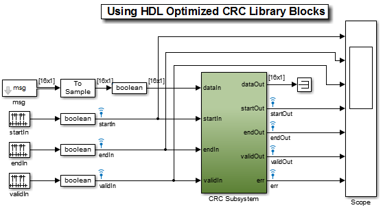
In this example, we want to analyze the relation between many signals, and how they transition over time. Without the Logic Analyzer, you would probably try to observe the signals using a Scope block:
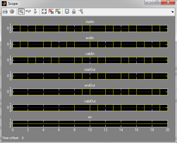
As you can see, analyzing the evolution of those 7 signals and their relation over time is not easy. With the Logic Analyzer, the same signals look like:
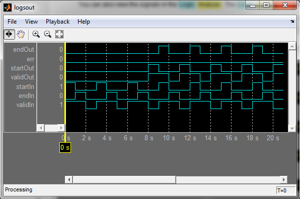
Guy: Wow, the advantage is pretty obvious. Now, can you give us some details on how to get started with the Logic Analyzer?
Getting Started with The Logic Analyzer
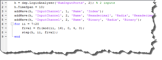
Kirthi: The first thing to note is that the Logic Analyzer is a System object. As with most system objects, you first need to instantiate it. Then you can programmatically configure the analyzer and add waves using the addWave method.
In the following example, we create a Logic Analyzer with 2 input ports and 3 waveforms. The second and third waveforms will be used to display the second input in two different ways.
Guy: Do I need to configure everything programmatically?
Kirthi: No! Everything you can do programmatically can be done using the user interface. Here is an animation illustrating that:
Here is another animation showing more possibilities of the Logic Analyzer like adding dividers, cursors and changing colors:
Now it's your turn
Try the new Logic Analyzer and let us know what you think by leaving a comment here.
- Category:
- What's new?


Comments
To leave a comment, please click here to sign in to your MathWorks Account or create a new one.