Simulating the World’s longest Ultra High Voltage Transmission Line with Simscape Electrical
This week, I am happy to welcome guest blogger Hao Chen who will describe how Simscape Electrical can be used to simulate the world's longest (3324 km) Ultra High Voltage DC (± 1100 kV) transmission system with the largest transmission capacity (24000 MW) in China.

Starting with an Example
Simscape Electrical includes a lot of examples. For most systems you could model, there is probably an example that you could use as a good starting point.
In this case, we will start with the example titled VSC-Based HVDC Transmission System (Detailed Model).
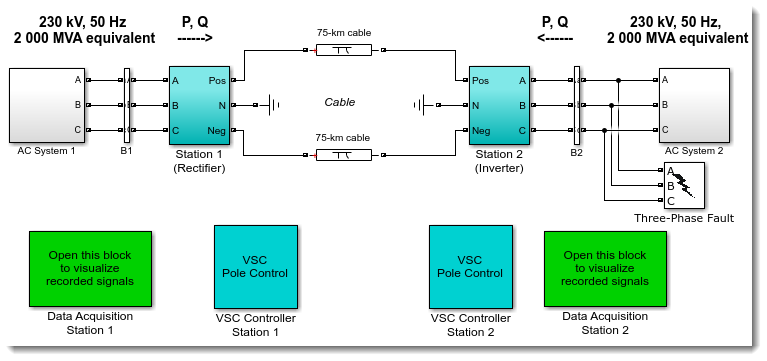
This example illustrates a 200 MVA (± 100 kV) voltage source converter-based HVDC system with 75 km transmission distance. If you are interested in the detailed system configuration and control design, I recommend visiting this documentation page:
https://www.mathworks.com/help/releases/R2017b/physmod/sps/powersys/ug/vsc-based-hvdc-link.html
Modifying the Example
With a few modifications, you may easily upgrade this example model to any of your desired HVDC systems. For example, after making the following changes, we can get the aforementioned most advanced HVDC system:
- Voltage and power ratings of transformers and AC filters in both converter stations
- Transmission cable parameters
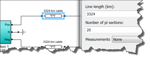
For example, for the transmission cabler parameters, this means changing the Line Length (km) from 75 to 3324 and increasing the number of pi sections accordingly in the dialog of the PI section Line block:
What to do with this model?
Starting from this specific model, you may accomplish the following typical tasks:
- Active/reactive power and DC voltage regulation
- Transient stability study under different disturbances
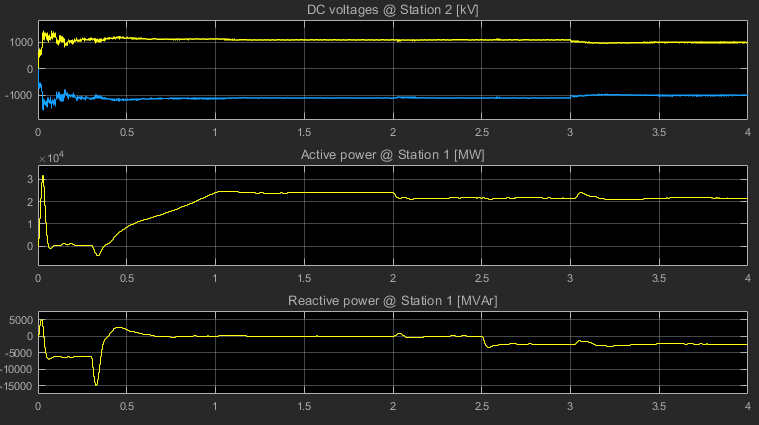
The following simulation results illustrate a steady-state operation/regulation of the system:
- After the DC voltages (± 1100 kV) are established at Station 2 (Trace 1: 0 second ~ 1 second), 24000 MW active power and 0 MVAr reactive power are transmitted at Station 1 (Trace 2 and Trace 3: 1 second ~ 2 second)
- At 2 second, the transmitted active power is decreased to 21600 MW
- At 2.5 second, the transmitted reactive power is decreased to -2400 MVAr which implies that the AC system1 absorbs 2400 MVAr reactive power from Station 1
- At 3 second, the DC voltages are controlled to be ± 1000 kV.
What's Next?
You could easily expand this model to include other components like wind power plants in the AC system at the Rectifier Station side. For your convenience, Simscape Electrical provides many wind turbine models including most popular configurations, such as fixed-speed induction generator-based wind turbines, doubly fed induction generator-based wind turbine, and fully rated converter-based wind turbines. Look at those examples for more details:
https://www.mathworks.com/help/releases/R2017b/physmod/sps/examples.html#d2e3515
- Category:
- Guest Blogger,
- Physical Modeling




Comments
To leave a comment, please click here to sign in to your MathWorks Account or create a new one.