
Bus Signals in the Generated Code
Blog reader Paul J. shared with us his mental model of the bus as a structure. While this isn’t true of virtual buses, it is precisely true of nonvirtual buses. In fact, when you generate the code for a nonvirtual bus using Real-Time Workshop, the result is a structure.
Focus on the boundaries
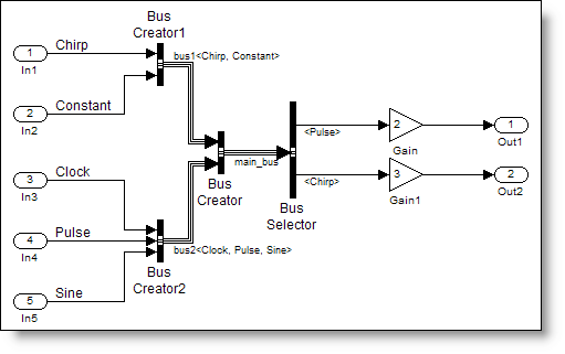
In a previous post about nonvirtual bus signals I talked about memory allocated for the bus. The places we have to think about memory allocation are the boundaries of systems. Here is the simplebusdemo_nv.mdl

This model has the root level boundaries defined by the inport and outport blocks. It also has a boundary at the edge of the ReusableFcn subsystem. The main_bus crosses this boundary and the generated code is different if the bus is virtual versus nonvirtual.
The ReusableFcn subsystem contains a Bus Selector and two gain blocks.

I configured the subsystem to generate a reusable function. Here are the settings for the subsystem:

Basically, I have specified how Real-Time Workshop should wrap up the algorithm implemented inside this system. By specifying “Treat as atomic unit”, the blocks inside the system execute together. Real-Time Workshop will generate reusable function code with my specified name (ReusableFcn) into a file of the same name (ReusableFcn.c). The reusable function code will pass input and output signals as arguments to the function.
I can now picture what this will look like:
ReusableFcn(inputs..., outputs...)
Virtual buses pass every element separately

When the bus signal is virtual at the inport to the ReusableFcn, only the elements of the bus that are used in the system need to be passed through the boundary. Here is the actual code for the function call:
30   /* Outputs for atomic SubSystem: '<Root>/ReusableFcn' */
31   ReusableFcn(simplebusdemo_vir_U.Pulse, simplebusdemo_vir_U.Chirp,
32               &simplebusdemo_vir_B.ReusableFcn_m);
33
Notice, there is no evidence in the code that a bus signal exists. At compile-time, direct connections between sources and destinations replace the virtual bus.
19 /* Output and update for atomic system: '<Root>/ReusableFcn' */
20 void ReusableFcn(real32_T rtu_0, real_T rtu_1, rtB_ReusableFcn *localB)
21 {
22   /* Gain: '<S1>/Gain' */
23   localB->Gain = 2.0F * rtu_0;
24
25   /* Gain: '<S1>/Gain1' */
26   localB->Gain1 = 3.0 * rtu_1;
27 }
Nonvirtual buses are structures
The nonvirtual bus is a contiguous block of memory. This is assembled and passed into the ReusableFcn.
30   /* local block i/o variables */
31   main_bus rtb_main_bus;
32
33   /* BusCreator: '<Root>/Bus Creator' incorporates:
34    *  BusCreator: '<Root>/BusConversion_InsertedFor_Bus Creator_at_inport_0'
35    *  BusCreator: '<Root>/BusConversion_InsertedFor_Bus Creator_at_inport_1'
36    *  Inport: '<Root>/In1'
37    *  Inport: '<Root>/In2'
38    *  Inport: '<Root>/In3'
39    *  Inport: '<Root>/In4'
40    *  Inport: '<Root>/In5'
41    */
42   rtb_main_bus.bus1.Chirp = simplebusdemo_nv_U.Chirp;
43   rtb_main_bus.bus1.Constant[0] = simplebusdemo_nv_U.Constant[0];
44   rtb_main_bus.bus1.Constant[1] = simplebusdemo_nv_U.Constant[1];
45   rtb_main_bus.bus1.Constant[2] = simplebusdemo_nv_U.Constant[2];
46   rtb_main_bus.bus2.Clock = simplebusdemo_nv_U.Clock;
47   rtb_main_bus.bus2.Pulse = simplebusdemo_nv_U.Pulse;
48   rtb_main_bus.bus2.Sine[0] = simplebusdemo_nv_U.Sine[0];
49   rtb_main_bus.bus2.Sine[1] = simplebusdemo_nv_U.Sine[1];
50
51   /* Outputs for atomic SubSystem: '<Root>/ReusableFcn' */
52   ReusableFcn(&rtb_main_bus, &simplebusdemo_nv_B.ReusableFcn_a);
Each of the input signals is being copied into the rtb_main_bus variable, which is an instance of the main_bus type. This structure matches the bus object definition specified by main_bus, bus1, and bus2.
I notice that the ReusableFcn has a shorter interface. Now the only input signal is a pointer to the rtb_main_bus, which is allocated locally.
19 /* Output and update for atomic system: '<Root>/ReusableFcn' */
20 void ReusableFcn(const main_bus *rtu_In1, rtB_ReusableFcn *localB)
21 {
22   /* Gain: '<S1>/Gain' */
23   localB->Gain = 2.0F * (*rtu_In1).bus2.Pulse;
24
25   /* Gain: '<S1>/Gain1' */
26   localB->Gain1 = 3.0 * (*rtu_In1).bus1.Chirp;
27 }
In the case of nonvirtual bus signals, the concept of interface specification using the bus object carries all the way down to the generated code.
Now it’s your turn
We have now covered most of the important topics on bus signals. What questions remain about bus signals and their use in your models? Post a comment here.
- Category:
- Code Generation,
- Signals


Comments
To leave a comment, please click here to sign in to your MathWorks Account or create a new one.