Seth on Simulink

June 13th, 2008

Announcing SimElectronics!

In early April, our physical modeling team released a new add-on for Simulink, SimElectronics. SimElectronics extends Simscape by adding tools for modeling electronics and electromechanical systems.

What is Simscape?

Simscape is a platform for physical modeling. Instead of connecting together blocks that define the equations of your system, Simscape and its add-on tools enable modeling and simulation of multidomain physical systems, such as those with mechanical, hydraulic, and electrical components. The connections between physical modeling elements are not signals, the connections don’t represent data flow. They represent physical connections between things like bodies and joints, or resistors and transistors.

What’s new with SimElectronics?

SimElectronics adds components for modeling electronics and electromechanical systems.

  • Includes semiconductors, actuators, sensors, and IC elements
  • Includes the ability to simulate in PWM or Averaged mode to balance the level of fidelity vs simulation speed
  • Import SPICE net lists containing Transistors, JFET, diode, sources, and passive SPICE components

I think it helps to look at the web demos to understand what you might do with SimElectronics. These demos have great SVG published models that you can explore. Start with this plant model of a DC motor connected to a worm gear as part of a linear actuator. This plant model might be your first step in developing a controller for such a system.

DC Motor and linear actuator plant model
(click for a WebView of the model)

Next, you might add an H-Bridge, a current controller, and a speed controller for the linear actuator. Take a look at this plant model with a controller.

DC Motor and linear actuator with a controller
(click for a WebView of the model)

This model would show that you have good controllers, but notice the controllers consist of transfer function pre-filters and PI controllers with Simulink integrator blocks. These controllers can now be modeled using SimElectronics components. The final step in the series would be a validation model with the op-amps, resistors and capacitors that would implement the controller you designed.

DC Motor and linear actutor with a implementation model of the controller
(click for a WebView of the model)

This model uses a 10 kHz PWM waveform to achieve a high fidelity simulation. Download a trial of SimElectronics if you think this type of workflow would be useful to you.

Video of SimElectronics in action

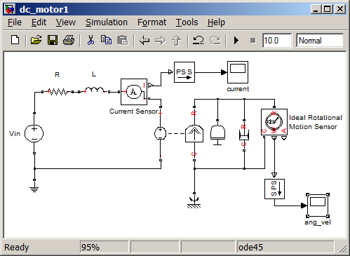
Steve Miller has made a video demo of Modeling an Electromechanical System. I recommend watching this to get the SimElectronics experience.

Now it’s your turn

Are you using the physical modeling tools? Have you tried SimElectronics? Post a comment here and tell us about it.

5 Responses to “Announcing SimElectronics!”

  1. mohsen replied on :

    dear sir, tnx for ur very good helping,
    I wanna exactly now from which release this new toolbox(simelectrinics) is add on and how I can install it on previous versions
    thank u in advance

  2. Seth replied on :

    @mohsen - SimElectronics was released as part of R2008a+, and is only compatible with that release.

  3. Bilal Majeed replied on :

    Dear Sir,
    Thanks for your release.That was realy helpfull. Sir i have a little problem in connecting my simulink block to my GUI. In actual my requirement is to get data from my simulink in real time and plot it in real time on my GUI AXES. like on scope of simulink block. Please help me out.
    Thanks in advance

    Regards,
    Bilal

  4. ljp replied on :

    very good

  5. fccu replied on :

    Great post! Thanks for sharing!! :D

Leave a Reply

Wrap code fragments inside <pre> tags, like this:

<pre class="code">
a = magic(3);
sum(a)
</pre>

If you have a "<" character in your code, either follow it with a space or replace it with "&lt;" (including the semicolon).


Seth Popinchalk is an Application Engineer for The MathWorks. He writes here about Simulink and other MathWorks tools used in Model-Based Design.
  • garla: what is advantage of exporting the bus object with the format as “cell” and “object” ....
  • J.r: @ Guy - Example sent to your account. Thank you.
  • Guy: @ J.r - The ability for atomic subsystems and Model Reference to remove the “fake algebraic loop”...
  • J.r: Sorry to hit an old thread, but this seems like the best place to solicit help on this topic. Is there supposed...
  • Bindu: please tell me how can i get the sampling time used in simulation
  • Seth: @Han - The basic change to the code is the addition of dimensions information. Each signal passed between...
  • Bindu: sir please help me to get the sampling time of a signal using ode 45 algorithm
  • Seth: @Jeff Newcum - Thanks for the photos! @Liz Nilsen - You are welcome! Your site is a great resource for STEM...
  • Liz Nilsen: I’ve got a large list of competitions at my blog - but I didn’t have EcoCar or Robocon -...
  • Jeff Newcum: Seth, thanks for the credit on the photos!

These postings are the author's and don't necessarily represent the opinions of The MathWorks.