
Metronome Challenge Winners
Two weeks ago, I posted the Challenge: Metronome Synchronization. The challenge was to model the synchronization of metronomes as observed in this video.
The results of the challenge tell an interesting story about the community effort to solve this modeling problem. Congratulations go out to our two winners, Thomas Steffen and Xianfa Zeng. I am awarding them both the highly coveted MATLAB Central Laptop bag. Let’s look over the major innovations they both contributed to this challenge.
Thinking about the original video, we can imagine the important elements of the system. The two major components of the models are the cart on which the metronomes ride, and the metronomes. I also posted a derivation of the system of equations that simplify the metronome down to a frictionless pendulum. However, a metronome is more than just a pendulum. It also contains springs, gears, and an escapement to put energy into the system and regulate the motion of the pendulum. In the real world, frictionless pendulums are uncommon. As we will soon find out, modeling a metronome as a frictionless pendulum is an over simplification.
Xianfa Zeng’s entry with improved animation
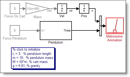
Xianfa Zeng submitted the entry: Metronome Synchronization.

Click here to see a web view of Xianfa’s model.
This model is a great example of clean block diagram layout. On the left are subsystems that implement each of the pendulums in a five-pendulum experiment, just like the video. The input to the pendulum system is the acceleration of the cart. The output from the system is the angle of the pendulum, and the force on the cart due to that pendulum.
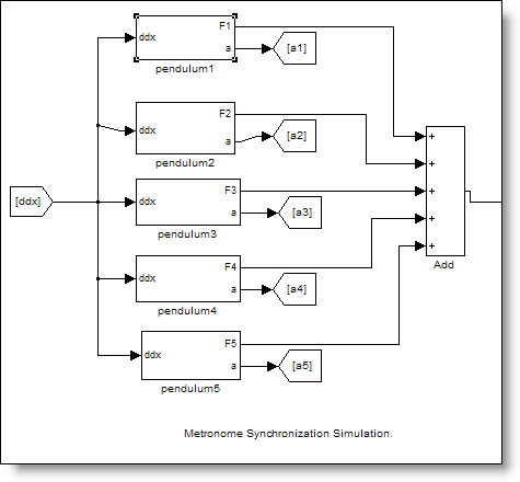
On the right are the dynamics of the cart. This sums the accelerations on the cart and integrates to find the position.

Xianfa also developed an excellent M-file S-function to animate the motion of the system. This went beyond the simple animation I initially provided.

Thomas Steffens’s insight into the nature of synchronization
Xianfa’s simulation laid the groundwork for Thomas Steffen’s submission: Metronome
with Driving Force. Thomas described his submission in this way:
Ok, my approach is very different from the ones I have seen.
I followed four premises:a) The pendulum is essential linear, and the nonlinearity of the angle is not
relevant. (This is an assumption, and I make no attempt to verify it.)
b) Any coupling between n resonators creates n resonance frequencies that are
diverging with increasing coupling, so no synchronisation here.
c) A metronome is driven by a spring to compensate for the friction, and the
direction of the force switches a bit after the metronome has passed angle 0.
d) Synchronisation happens because the shared based shifts this switching point
to earlier or later (the angle remains the same).Just run the file, and you will see it happening pretty soon. This model is based
on the Simulink model of Xianfa Zeng, which is a really nice framework. The
pendulum model is very different, though. Both are inspired by "Challenge:
Metronome and Cart Equations of Motion" on Seth's blog.

Click here to see a web view of Thomas’ model.
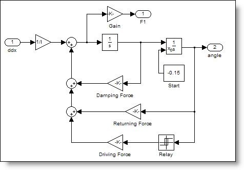
Thomas added an important element to the system that was missing from the others. He introduced a non-linearity to the system in the way of a driving force. I imagine it like this. As the pendulum moves further from center, the force of gravity pushing it back to the center is proportional to sin(θ). A common approximation is sin(θ)=θ for small values of θ. The angles of the pendulum are generally small, so the system is essentially linear. Thomas also commented that:
Synchronisation cannot happen in a linear framework, that is
a long known fact from electrical oscillators. Coupling them leads to several
modes with slightly different resonance frequencies (”off tune”), and
increasing the coupling separates the frequencies further.So the key is nonlinearity. My guess is that it is the
driving force, but I did not study other options.
Thomas’ pendulum model includes this driving force:
The plot tells the full story. Here are three different periods of Thomas Steffen’s simulation. First, here is a graph near the beginning at 5 seconds. The yellow line is the position of the cart.
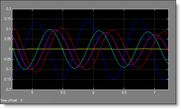
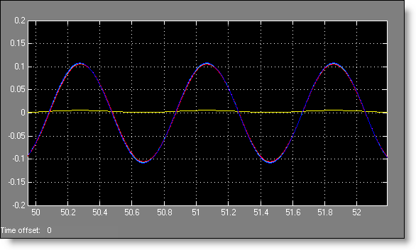
You see that there is no synchronization. The next period is at 28 seconds.

The pendulums are very, very close to synchronization. Finally, after only 50 seconds, the lines are on top of each other.
Congratulations to Thomas and Xianfa
Don’t let the conclusion of the challenge stop you. We have only investigated a small portion of metronome synchronization problem. The benefit of a model is the ease with which you can ask questions and find
answers. There are many open questions as well as new challenges awaiting us. Would you like to propose another modeling challenge? Do you want to see a review of how some MathWorkers attempted this modeling problem? Leave a comment and share your thoughts.
- Category:
- Challenge,
- Community,
- Modeling


Comments
To leave a comment, please click here to sign in to your MathWorks Account or create a new one.