Guy and Seth on Simulink

May 22nd, 2009

Robotic Arm Models and Repairing Hubble

As you may know, Space Shuttle Atlantis is about to return this weekend from man’s last visit to the Hubble Telescope.  Those astronauts took some major risks to repair our favorite and most famous scientific instrument.  One of the tools they used during space walks is the robotic manipulator from the Canadian Space Agency (the robotic arm).

Image Source: Nasa - STS125 Hubble above the space shuttle Atlantis cargo bay

Image Credit: NASA

I have never had a chance to operate a CSA robotic arm, but my colleague Guy Rouleau has!  Guy told me about a Simulink S-function he created to help in controlling a robotic arm in Simulink.

Changing the color of blocks during simulation

By Guy Rouleau

Roboticist Guy Rouleau

I have many good memories from my internship at the Canadian Space Agency when I was studying for my bachelor degree.  During this internship, I was developing control logic for a robotic arm. Simulink was used to develop the controllers and as a user interface to command the robot.

Using a joystick to control inputs to a Simulink model of a robotic arm.

When driving a robotic arm simulation using a joystick, it is not always easy to visualize if you are close to a joint limit or a singularity. It is possible to display the state values in the model, but hard to know if you are about to lock out control of the arm.  To help the person driving the robot, we though it might be cool to make blocks in the Simulink diagram turn red when close to a limit.  This is what it looks like in action with the SimMechanics mech_robot_vr.mdl model.

Animation of a virtual reality robotic arm with red and green displays to indicate joint state.

Here is a quick explanation of how to changing the color of a block with a simple Level 2 M-file S-Function.

As a template, I suggest starting with the demo M-file msfcn_times_two.m. In your MATLAB installation, you can open this file using the following command:

>> edit msfcn_times_two.m

Only a few modifications are required to make the file change the color of a block based on the value of the signal connected to the s-function.

To begin, save the file as ChangeColor.m for this example. At the minimum, you need to modify the code of the Output section. To start, I created a model named “Test” where we will change the color of the block named “Display”

Simulink test model to show the S-function working.

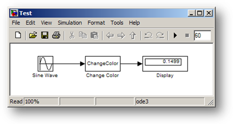
The simplest implementation can look at the input value, and then use set_param to modify the block BackgroundColor:

Outputs code for the S-function

In the above code, the color of the block “Test/Display” is set to green or red depending if the input is larger or smaller than zero.

In order to make the code reusable, I may want to determine automatically which block is connected to the S-Function. We can also add a parameter to the block to set the value at which the color switches. In that case, we add these lines to the setup function:

Block setup code

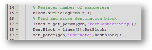
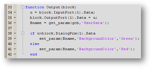
Notice that the handle to the destination block is stored in the “UserData” of the S-function. UserData is often useful for storing any data you need to persist with the S-function, but doesn’t fit the definition of a continuous or discrete state. The output function now looks like:

Block outputs using User Data to get the block handle

Finally, if you want the block to return to white at the end of the simulation, you can add these lines to the terminate function:

Terminate function that sets the block back to white background.

You can find this example in my File Exchange Submission: Changing the color of a block while the simulation runs.

Now it is your turn

Do you work on a robotic arm or on the Hubble?  Have you used an S-function to customize what Simulink looks like?  Share your experience and leave a comment here.

13 Responses to “Robotic Arm Models and Repairing Hubble”

  1. SYED MURTUZA HUSSAIN replied on :

    Good Evening,

    I’m glad to see you webpage,it gives me many ideas to work and study of robotics.

    Thanking You.

  2. rienzi mosqueda replied on :

    hi.!im currently into the studying a robotic arm and possibly simulating one by controlling it by a joy stick..could you possibly send me some infos on your program the casing of your arm etc..tnx

  3. Seth replied on :

    @Syed Murtuza Hussain – Happy to provide some inspiration.

    @Rienzi Mosqueda – The example models I would share with you are part of the demos in SimMechanics. They all depend on the SimMechanics product, so they would not work unless you have a license. Some of the product demos are indexed on mathworks.com here:
    http://www.mathworks.com/products/simmechanics/demos.html

  4. Renish replied on :

    clc;
    clear all;
    % To Open a new model file the Existing Model
    % new_system(‘Chaining_Diagram’,'Model’)

    % To Open the Existing Model
    open_system(‘Chaining_Diagram’)
    Pos = [115, 88, 155, 122];
    for i = 1:3
    % To add a block to the model
    h = add_block(‘simulink/Ports & Subsystems/Subsystem’, ‘Chaining_Diagram/Subsystem’, ‘MakeNameUnique’, ‘on’);
    if i == 1
    add_block(‘simulink/Sources/In1′,’Chaining_Diagram/Subsystem/In1′, ‘MakeNameUnique’, ‘on’);
    add_block(‘simulink/Sinks/Out1′, ‘Chaining_Diagram/Subsystem/In1′, ‘MakeNameUnique’, ‘on’);
    else
    path = strcat(‘Chaining_Diagram/Subsystem’,num2str(i-1),’/In1′);
    add_block(‘simulink/Sources/In1′, path, ‘MakeNameUnique’, ‘on’);
    add_block(‘simulink/Sinks/Out1′, path, ‘MakeNameUnique’, ‘on’);
    end
    % To set the Dimension of the block
    set_param(h, ‘Position’, Pos)
    set_param(h, ‘ShowPortLabels’,'off’)
    BlkName = strcat(‘disp(‘,num2str(i),’)');
    set_param(h, ‘MaskDisplay’,BlkName)
    set_param(h, ‘ShowName’,'off’)
    set_param(h, ‘Mask’,'on’)
    Pos = Pos + [0, 100, 0, 100];
    end
    add_line(‘Chaining_Diagram’,'Subsystem/1′,’Subsystem2/2′,’autorouting’,'on’)
    add_line(‘Chaining_Diagram’,'Subsystem/2′,’Subsystem1/1′,’autorouting’,'on’)
    add_line(‘Chaining_Diagram’,'Subsystem1/1′,’Subsystem2/1′,’autorouting’,'on’)
    add_line(‘Chaining_Diagram’,'Subsystem1/2′,’Subsystem/2′,’autorouting’,'on’)
    add_line(‘Chaining_Diagram’,'Subsystem2/1′,’Subsystem/1′,’autorouting’,'on’)
    add_line(‘Chaining_Diagram’,'Subsystem2/2′,’Subsystem1/2′,’autorouting’,'on’)

    % To save the open System
    save_system(‘Chaining_Diagram’)
    %*************************************************
    please help me to avoid overlapping of lines when this piece of code Executes.
    THanks in advance

  5. manju replied on :
    I want to know the state space model of two arm robot manipulator.
    
  6. Simone Leon replied on :

    I am an Mphil Student at the University of the West Indies, St. Augustine, Trinidad & Tobago – Faculty of Mathematics and Computer Science. Presently my studies are in emotional recognition in artificial systems using Matlab Simulink as a simulation tool and PSO Models and how it can be applied to Emotion-Oriented eCommerce Systems.

    I have been researching extensively on existing Simulink Control models which are able to simulate the emotions of a user. Such a Model should possess a stated emotional model. However, at this juncture my research is proving futile.

    I would like to know if there are actually any Simulink Control Models created in Matlab that can simulate the emotion of a customer or user and how can they be accessed. I do not want to reinvent the wheel if such a project has already been done. The aim is to use an existing simulation to support my findings. This system will be well referenced in the final production of my thesis.

    Do you therfore have an emotional model simulated in Simulink and PSO? If this is available for review, can you make the Model available for further analysis?

    Your help and suggestions would be greatly appreciated.

  7. Seth replied on :

    @Simone Leon – while I have talked to people about modeling financial systems and biological systems, I have not seen any “emotional models.” I suggest you reach out to a larger community (like comp.soft-sys.matlab) to find an answer. If you have a clear idea of what states your are modeling, and the conditions that lead to transitions between those states, it will be easily expressed in a Stateflow chart.

  8. Simone Leon replied on :

    Are there then any matlab/simulink programs used for recognizing and simulating happy,sad,joy,nervousness,disgust etc….

  9. Simone Leon replied on :

    To be a little more detailed, are there then any matlab/simulink stateflow diagrams or programs used for recognizing and simulating happy,sad,joy,nervousness,disgust etc…. I now there are emotion and face recognition programs in matlab. However, I have not seen any stateflows diagrams that would represent such a simulation. Are there any?

  10. Albert replied on :

    What is the free website that I can refer to if I want to use Matlab to impelent my PSO application? Thank you.

  11. Villy replied on :

    Hi!

    I am currently working on a robotic simulation using matlab-simulink, Solidworks and possibly Simulink VR tool.
    I do like the idea of controlling it with several external joysticks. How can I “connect” the joysticks to the model?

  12. Guy Rouleau replied on :

    @Villy,

    Simulink 3D Animation includes a block to process input from a joystick device:

    http://www.mathworks.com/access/helpdesk/help/toolbox/sl3d/joystickinput.html

    Aerospace Blockset also provides a similar block:

    http://www.mathworks.com/access/helpdesk/help/toolbox/aeroblks/pilotjoystick.html

  13. Aliza replied on :

    Hi,
    I am working on a simulink model with a number of other people. I am interested in color coding changes done by each person. So that if a parameter of a block was changed, or if a block was added etc. i would like those blocks to have their background color changed automatically according to the color assigned to that person.
    Is there any way to do this?

Leave a Reply

Wrap code fragments inside <pre> tags, like this:

<pre class="code">
a = magic(3);
sum(a)
</pre>

If you have a "<" character in your code, either follow it with a space or replace it with "&lt;" (including the semicolon).


MathWorks
Guy Rouleau and Seth Popinchalk are Application Engineers for MathWorks. They write here about Simulink and other MathWorks tools used in Model-Based Design.

These postings are the author's and don't necessarily represent the opinions of The MathWorks.