Guy and Seth on Simulink

February 4th, 2010

New (Since R2009a) Simulink inside Stateflow

This week I asked Michael Carone to introduce a relatively new Stateflow capability, Simulink Functions.

Stateflow expert Michael Carone

Did you ever want to put a Simulink block inside of a Stateflow chart?  Well, if you have R2009a or R2009b, you can!

Simulink subsystems inside Stateflow Charts.

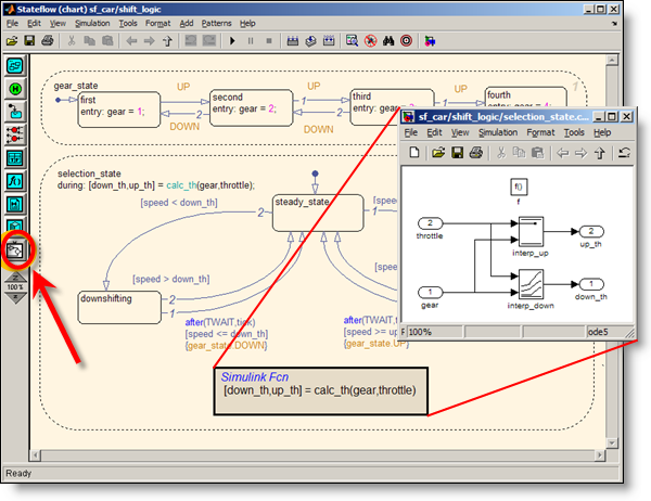
When you open your Stateflow chart, you’ll see a new white button that looks like a Simulink subsystem on the bottom of the graphical palette.  Use that button to drag in a Simulink function (just like you would for an Embedded MATLAB function), double-click on the function, and you have a Simulink window for creating your new Simulink function.  Or if you have a function already built in Simulink that you want to embed in Stateflow, just copy and paste that block from Simulink into Stateflow (new for R2009b).

Now some of you might be asking, “Why would I want to do this?”  Well, there are a few applications that immediately come to my mind.  Maybe you have an algorithm you already designed in Simulink that you want to reuse in Stateflow.  Or maybe you want to use Stateflow to schedule exactly when to trigger a specific task or controller.  You might also want to control the behavior of separate components modeled in Simulink. 

Check out this MATLAB Digest article if you want to see some design patterns for using Simulink functions in Stateflow.  There’s also a simple demo here you can check out.  Or go to the documentation if you really want to get all the details.

Now it’s Your Turn

Can you see how embedding Simulink functions in Stateflow charts would be helpful for your models?  Leave a comment below and let me know.

8 Responses to “New (Since R2009a) Simulink inside Stateflow”

  1. wei replied on :

    @Michael, Would you explain how parameter, e.g. ‘k’ for a gain block in Simulink function, is handled?

  2. Robert Stokes replied on :

    So can you add new ‘simulink functions’ and change their parameters programmatically through a *.m file?

  3. Rob Aberg replied on :

    @Robert Stokes: Yes, you can work with parameters the normal way – the functions are real Simulink function call subsystems inside the chart. For example, if you click on the interp_down lookup table block in the example, it becomes the editor’s current block and you can get its name via the “get current block” command, gcb:

    >> gcb
    ans =
    
    sf_car/shift_logic/selection_state.calc_th/interp_down
    
    >> get_param(gcb,'Table')
    ans =
    
    downtab
    

    In this example, the downtab variable that defines the table is stored in the sf_car model workspace, but it could be stored in Stateflow’s data dictionary or in the MATLAB base workspace. You can use MATLAB code in a *.m file to define or manipulate the value of downtab, or manipulate the block directly using set_param(block,property,value) commands.

  4. wei replied on :

    @Rob, Thank you for replying. How do I store Simulink function block parameter in Stateflow data dictionary and with chart scope?
    Does Simulink support mask subsystem and how mask variable is handled?

  5. Seth replied on :

    @wei – The mental model I use for a Simulink function is similar to an MATLAB function. The interface is defined by the function signature. Each input is an inport, each output is an outport. This provides an interface to the Simulink function subsystem.

    Masking is a means for providing simplified graphical interface to a subsystem. The Simulink function doesn’t have a graphical interface because the “block” is like a prototype for the function. Each call site within the state chart/flow diagram pass data through the interface into the system. You can parameterize each of the call sites as needed.

    Try it out and let us know how it works for you.

  6. M Hakkeem replied on :

    I want to track my transition action from default transition to end active transition while running the model

  7. Steffen replied on :

    @Rob Aberg: You mentioned that inside a simulink function variables can be used that are defined in the Statflow data dictionary. I tried doing this but get the error message that the parameter cannot be evaluated.

  8. Michael Carone replied on :

    @Steffen: Even though the data is stored in the Stateflow data dictionary, you also need to pass the data into the function that you are calling, whether it’s a Simulink function or a MATLAB function. For example, if you open the sf_car model, you’ll see that the “gear” and “throttle” arguments are passed into the Simulink function. And if you open the Model Explorer, you’ll see that those two variables are stored within the Stateflow data dictionary.

Leave a Reply

Wrap code fragments inside <pre> tags, like this:

<pre class="code">
a = magic(3);
sum(a)
</pre>

If you have a "<" character in your code, either follow it with a space or replace it with "&lt;" (including the semicolon).


MathWorks
Guy Rouleau and Seth Popinchalk are Application Engineers for MathWorks. They write here about Simulink and other MathWorks tools used in Model-Based Design.

These postings are the author's and don't necessarily represent the opinions of The MathWorks.