
Estimating Continuous-Time Transfer Functions with System Identification Toolbox
Today guest blogger Pravallika describes how she used new features of the System Identification Toolbox to design a controller for a DC motor
 Any controls engineer knows that the key to designing a good controller is having a good plant model. But what do you do if you don’t have the underlying equations?
System identification can help in that case. In R2012a, the System Identification Toolbox added support for estimating parameters of a model type that is most intuitive and easiest to work with for controls engineers – continuous-time transfer functions. You can specify how many poles and zeros you want your transfer function to have, and the toolbox determines locations of poles and zeros automatically. If the system you are trying to model has a delay, the toolbox can automatically determine its value.
The Setup
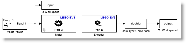
I have been working with the setup shown in the image below. It is very simple; it is a small DC motor connected to an Arduino board.

I applied a voltage to the motor and recorded the resulting motion. I imported this data in MATLAB and constructed an iddata object.

Here is what the data look like, using the iddata plot command.

Estimation
Let’s begin by estimating the simplest possible transfer function – first-order, with no zeros. For that, we use the new function tfest.

After the estimation is completed, we can compare the output of the model with the measured shaft angle. The comparison shows that the model does a good job in capturing dynamics of the motor.

Validation
To ensure that the estimated transfer function represents motor dynamics, we need to validate this transfer function against an independent data set.
I tried feeding other sets of data acquired experimentally through the identified transfer function and compared the result with the measured shaft angle. Even though the fit is not perfect, the identified transfer function does a pretty good job in capturing system dynamics.

Using the Estimated Transfer Function
Now let's use the identified transfer function model to design a PID controller using pidtune.

One notable quality of models obtained with System Identification Toolbox is that they not only contain the information about the “nominal” parameter values, but also carry information about parameter uncertainty. We can check the effect of this parameter uncertainty on the bode plot magnitude of the estimated transfer function.

We can also use the function rsample to sample this parameter uncertainty to create an array of transfer functions to test our controller.


The plot above shows the closed-loop step response for the nominal plant as well as the additional ten step responses for the sampled parameter uncertainty. We can see that the PID controller we designed works well in the face of uncertainty in estimated transfer function parameters.
Estimating Other Model Types
In addition to estimating continuous-time transfer functions, System Identification Toolbox lets you estimate continuous-time state-space models and process models (special, low-order transfer functions). You can quickly compare different models and pick the one that is most appropriate for your problem.
Now it is your turn
How do you develop plant models? Try using new capabilities for continuous-time transfer function estimation and let us know what you think by leaving us a comment here.
- Category:
- Controls,
- Modeling,
- What's new?


Comments
To leave a comment, please click here to sign in to your MathWorks Account or create a new one.