
New for R2013a: Time Scope with Triggering!
Today we are happy to welcome guest blogger Kirthi Devleker to talk about a new trigger functionality added to the Time Scope in R2013a.
Did you know that a Trigger functionality is now available with the Time Scope in the DSP System Toolbox (R2013a) ? The Time Scope ships both as a System object and also as a Simulink block with the DSP System Toolbox


Triggers are ubiquitous on real-world hardware oscilloscopes. They are useful to analyze signals,specifically to stabilize a repetitive waveform and search for a occurrence of a particular pattern in the signal.
Trigger Modes:
The Trigger in Time Scope supports 3 different modes of operation for a given trigger type. They are:
- Auto: In this mode, the Time Scope stabilizes the display if the trigger criteria is met or continues to display the incoming signal.
- Normal : The time scope displays the stabilized signal only if the trigger criteria is met otherwise nothing is displayed.
- Once: The time scope displays the signal only for the very first time the trigger event is encountered. (Simulation will still keep running)
Here is an animation showing those different modes:

Let's look at a few more examples
Edge Triggering
Let's create a simple sine wave and display it on the Time Scope.
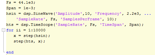
As soon as you click the Trigger button, the triggers panel open allowing you to configure options like level, type, polarity, etc.
Runt Triggering
What are Runt signals? Runt signals are the signals which typically cross a voltage threshold level but fail to cross a second threshold before re-crossing the first threshold level. Runt signals are frequently encountered in digital circuits.
For example if we look at the following waveform:
To look for Runt signals, Let us enable the Trigger, set the Trigger Mode to Normal, set the trigger type as Runt, adjust the voltage threshold and then the Time Scope detects and displays the presence of any Runt signals in the incoming data stream.
Now it's your turn
Go through the trigger documentation, give this a try and let us know what you think by leaving a comment here.
- Category:
- Signals,
- What's new?


Comments
To leave a comment, please click here to sign in to your MathWorks Account or create a new one.