Banking on the Hyperloop
This week, Matt Brauer is back to improve his three-dimensional analysis of the hyperloop transportation concept to include banking of the vehicle within the tube.
No, this hasn’t become a financial blog
As a quick disclaimer; this post does not cover the financial challenges of introducing a new form of transportation. Instead, we’re focusing on modeling the dynamic effects of a banked turn. As commenters on previous posts have pointed out, the g-forces felt by passengers of the Hyperloop would be reduced by the effects of the vehicle banking within the tube.
I’d like to share how I modeled banking and what effect it had on previously shared results.
Planar Dynamics
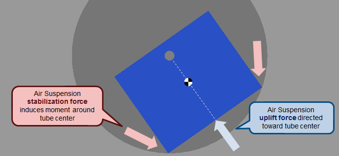
I started with the assumption that there is always sufficient force from the air suspension to keep the craft floating above the tube floor. I split the air suspension forces into an uplift force directed toward the center of the tube and a stabilization force influencing the craft’s rotation.

To this system, I can add centripetal forces calculated from the curved path of the tube to obtain a good idea of the accelerations experienced by the passengers.
SimMechanics Implementation
One simple way to model this system is using a Revolute Joint in SimMechanics.
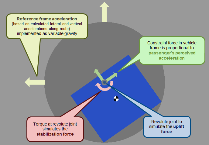
In the figure below, you can see a schematic representation of how the Revolute Joint is used. this includes:
- The centripetal acceleration calculated from the curved path is applied to the tube reference frame using the Time-Varying Gravity option of the Mechanism Configuration block.
- A torque is applied at the Revolute joint to control the banking and keep the vehicle in an optimal angle
- Constraint Forces are output from the Revolute Joint. Measuring these forces in the frame of the vehicle and dividing out the vehicle mass gives the horizontal and vertical g-forces felt by the passengers.

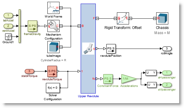
and in SimMechanics the implementation looks like this: (note the colors match the schematic above)

The Results
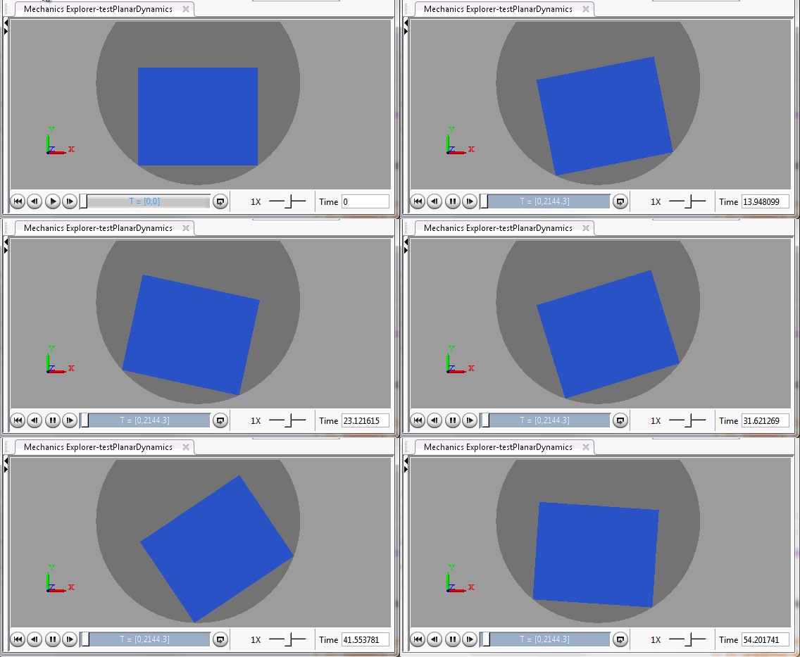
The Mechanics Explorer gives a visualization of the results. Here’s how the first minute looks:

I know my CAD renderings are embarrassingly basic. But, we’re working on something better for next time.
As expected, banking of the vehicle greatly reduces the lateral accelerations from the route curves. The plot below shows lateral (top) accelerations from static calculations (red) and dynamic results (blue).

The results indicate that it should be possible to tighten up some of the curves along the route. This should enable the Hyperloop to more closely follow the highway.
Now it's your turn
Retreive Matt's Hyperloop repository on GitHub and let us know what you think by leaving a comment here.


Comments
To leave a comment, please click here to sign in to your MathWorks Account or create a new one.