
Arduino Engineering Kit
Have you heard of the Arduino Engineering Kit?
If you are interested in DIY projects and are looking for a fun way to apply some control and robotics principles to a real system, you probably want to read this post.
Introduction
If you have been following this blog for some time, you are probably aware that I like using MATLAB and Simulink for various projects at home. For an example, see my sous-vide cooking machine posts.
When I heard that Arduino is now offering an Arduino Engineering Kit and that we have support packages to program it with Simulink, I contacted the team that put it together and asked if I could borrow one to play with it a bit.
When you buy the kit on the Arduino Store, you receive a box full of mechanical and electronic parts, including a Arduino MKR1000:

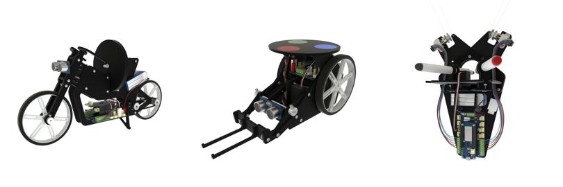
The kit includes instructions to build three possible projects: a motorcycle, a rover, or a drawing robot.

I decided to go for the motorcycle. I thought the inertia wheel making it self-balancing would be an interesting control project.
Getting Started
Once you have the kit pieced together, you will need to install a few packages in MATLAB:
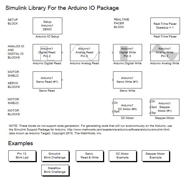
- Simulink Support Package for Arduino Hardware: This is the basic package you need to deploy Simulink models on the family of Arduino boards.
- Arduino Engineering Kit Hardware Support: this package contains the drivers and example models for all the sensors and actuators available in the kit.
- Arduino Engineering Kit Project Files: This package contains Simulink models specific to the three projects, both for simulating the systems and deploying on the hardware.
The easiest way to install those is through the Add-ons menu in the MATLAB toolstrip.
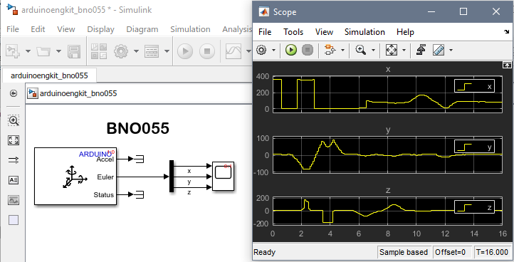
After installing those three packages, I went in the examples folder of the Arduino Engineering Kit Hardware Support package and tried the examples one by one, to be sure I was able to utilize all the sensors and actuators. For example, here is my test of the IMU, where I tilted the motorcycle by 90 degrees back and forth along all axes. This allowed me to conclude that the axis I want to control, the roll angle of the motorcycle, is the second element of the Euler angles output, the Y axis.
My Model
The Engineering Kit Project Files also contain a complete model that balances the motorcycle and allows you to control its speed and steering angle. However I thought it would be more fun to build mine from scratch. If you are interested, you can download the final version here.
Here is a picture of the top level of the final result.

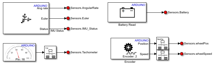
Let's look at each of the components. To begin, on the left I created a subsystem with all the sensors I needed and combined them in a Bus.
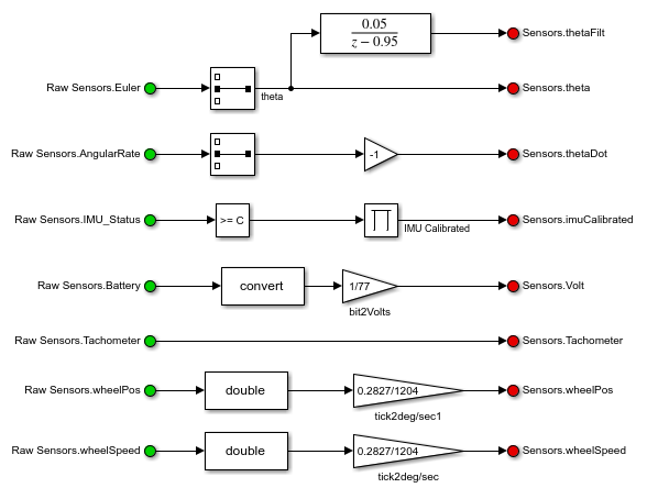
Next I process each sensor to extract the relevant data in convenient engineering units.
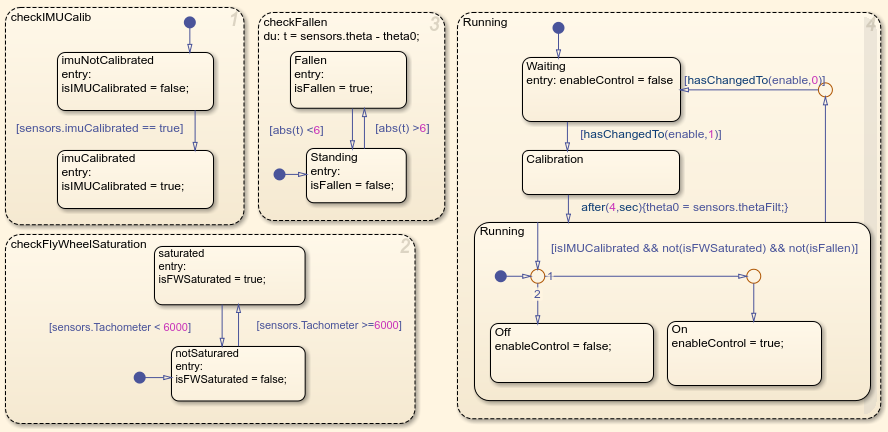
Now it is time for the Stateflow chart acting as the brain of my model. On the left, I check for three conditions: That the IMU is calibrated, that the motorcycle has not fallen, and that the flywheel does not reach maximum speed. When all those conditions are met, I can then click the Start button at the top level of the model. Once this is clicked, I have 4 seconds of calibration where I hold the motorcycle perfectly vertically for calibration before I start the balancing. If the motorcycle falls, I can hit the button again to reset the controller and try again.
When the chart enables the balancing, it turns on an Enabled Subsystem that activates the controllers. For the balancing fly-wheel, the controller is a PID that takes as input the roll angle of the motorcycle and generates a voltage command to the fly-wheel. For the motorcycle speed, this is a simple proportional controller, which takes as input the speed of the motorcycle, integrates it and compares it with the wheel encoder.

Note that this balancing controller is not perfect. The sensors on the fly-wheel motor do not allow direct measurement of the fly wheel velocity, making it difficult to control the fly-wheel motion perfectly. We are working on that!
Finally, the output of the controllers is sent to the output driver blocks.

And it works!
Here is a video showing the motorcycle in action:
Visit the Arduino Engineering Kit YouTube channel to see more examples.
Now it's your turn
Let us know what you think of the Arduino Engineering Kit in the comments below.
- Category:
- Challenge,
- Community,
- Fun,
- What's new?


Comments
To leave a comment, please click here to sign in to your MathWorks Account or create a new one.