
Challenge: Metronome and Cart Equations of Motion
I haven’t seen much activity on the Metronome Synchronization Challenge, so I want to provide a peak at the basis for my solution. I took the approach of modeling a pendulum, and then linking its dynamics to the dynamics of a cart. The challenge is choosing the right coordinate systems to assign to each of these bodies, even though they move together.
The Pendulum
If the
pendulum was all by itself, we could describe its motion by modeling the angle,
![]() , as it deflects from vertical. The
only force on the pendulum bob is gravity. Because the pendulum is constrained
to rotation about the pivot point, we only need the component of gravity in pendulum
frame of reference.
, as it deflects from vertical. The
only force on the pendulum bob is gravity. Because the pendulum is constrained
to rotation about the pivot point, we only need the component of gravity in pendulum
frame of reference.
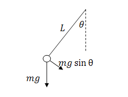
If we incorporate the motion of the cart, we find the linking of the acceleration of the cart to the acceleration of the pendulum bob. If the cart is accelerating, the reference frame of the pendulum accelerates, and this means that the pendulum will experience an opposite force/acceleration.
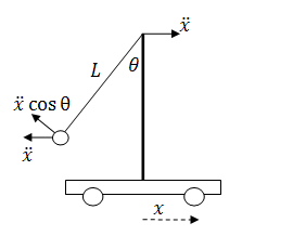
Combining
these two ideas in the ![]() frame centered on the pendulum pivot,
we can write the pendulum equation of motion.
frame centered on the pendulum pivot,
we can write the pendulum equation of motion.
![]()
Momentum in the system
To
understand the acceleration of the cart, I want to look at the change in the ![]() component of the momentum. Here are
some definitions:
component of the momentum. Here are
some definitions:
Length of
the pendulum: ![]()
Mass of the pendulum bob: ![]()
Mass of the cart: ![]()
The momentum
of the pendulum bob in the ![]() direction
direction
![]()
The momentum of the cart is
![]()
The friction
of the cart on the surface is the only resistance I want to model in the system,
and we can describe this force as proportional to the velocity, ![]() . This represents of the change of
momentum.
. This represents of the change of
momentum.
![]()
Combine
these terms to describe the momentum in the ![]() direction.
direction.
![]()
Up to this
point, I have looked at the problem of a single pendulum on a cart. Adding
another pendulum is just another momentum term, and to keep track of the
pendulums we will introduce ![]() and
and ![]() .
.
![]()
Taking the derivative of this equation gives us the acceleration of the cart:
![]()
System Equations
This equation for the cart, along with the dynamics of the pendulum provides the equations of motion for the system. Rewriting these as the highest order derivatives gives us something we can create in Simulink.
![]()
![]()
![]()
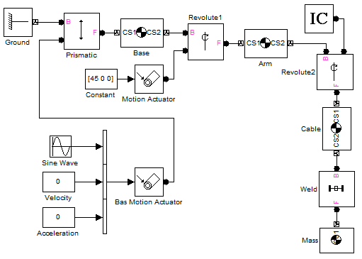
Are you up to the challenge?
Can you modify the model I provided in my last post to implement these equations? Post your solution by October 15th to the File Exchange with the keyword metronome.
- Category:
- Challenge,
- Modeling,
- ODEs


Comments
To leave a comment, please click here to sign in to your MathWorks Account or create a new one.