Guy and Seth on Simulink

August 20th, 2009

A Better If-Else Construct

In a previous post, I answered a question about how to model an If-Else behavior.  Here I will restate the algorithm I want to create:

if(sel==0)
out = 2*in1;
elseif (sel==1)
out = 3*in2;

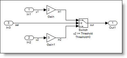
The first answer I gave relied upon a Switch block and the Conditional Input Branch Execution optimization to get an efficient If-Else construct in the model.  While this works, I don’t like reliance on an optimization to provide good behavior.  Sometimes, small changes to the model prevent Simulink from applying an optimization.  I think it is best to implement requirements explicitly.  In this post, I want to show you a way to model explicitly an If-Else conditional execution behavior.

Conditionally Executed Subsystems and Merge

The If-Else construct requires decision logic to control the execution of algorithm contained within the expression.  One way to do this is using the If block (from the Ports & Subsystems library), combined with the If Action Subsystem.  The If Action Subsystem executes based on the conditional expression in the If block.  If you have used Function Call subsystems, this is very similar.

The If Else, Else If, Action construct in Simulink blocks.

The If block provides control over If and ElseIf conditions, and there is even an option to provide an Else signal.

The Simulink If Block parameters.

This model will give you the conditional execution of the two subsystem, however, the subsystems write their outputs to separate signals.  How do you get two subsystem to write to the same signal?
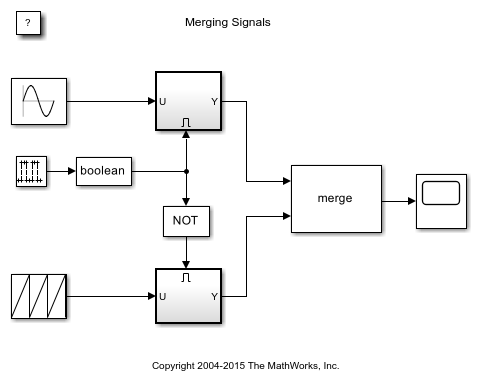
Merge the Signals

The Merge block provides a way for both subsystems to write to the same signal.

The Merge Block provides a way to specify that multiple signal write to the same memory location.

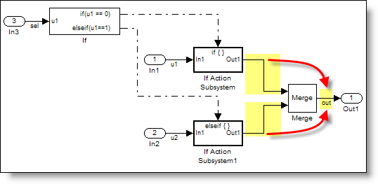
In many ways, the Merge block doesn’t behave like a block with the traditional input/output relationship.  I think of it more like a jumper across multiple wires.  The merge block specifies that all signals connected to it have the same value and actually share the same memory.  This is the programming practice of specifying multiple writers to the same variable.

Generated Code with Merge

The code generated from the above model looks a lot like our original algorithm.

   34     /* If: '<Root>/If' incorporates:
   35      *  ActionPort: '<S1>/Action Port'
   36      *  ActionPort: '<S2>/Action Port'
   37      *  Inport: '<Root>/In3'
   38      *  SubSystem: '<Root>/If Action Subsystem'
   39      *  SubSystem: '<Root>/If Action Subsystem1'
   40      */
   41     if (sel == 0.0) {
   42       /* Gain: '<S1>/Gain' incorporates:
   43        *  Inport: '<Root>/In1'
   44        */
   45       out = 2.0 * u1;
   46     } else {
   47       if (sel == 1.0) {
   48         /* Gain: '<S2>/Gain' incorporates:
   49          *  Inport: '<Root>/In2'
   50          */
   51         out = 3.0 * u2;
   52       }
   53     }

Correct use of Merge

Because Merge blocks are a memory specification rather than an algorithmic construct, there are some guidelines for using merge blocks.  The documentation shows some correct and incorrect usage patterns.  If you use merge block in your model, I suggest you run the Model Advisor Check for proper Merge block usage.

Now it’s your turn

Do you use the Merge block in your models?  Leave a comment here and share your experience.

10 Responses to “A Better If-Else Construct”

  1. Bob replied on :

    A topic that has caused great trouble over the years. As you mention, Simulink doesn’t always apply the conditional execution optimization (code that has states is a common reason here) and so it is generally required that developers use the If/Action or the Switch/Action (a great alternative to an If block with u1==0, u1==1, u1==2,…).

    These always draw complaints about how many lines one needs to connect properly, how easy it is to make a mistake, and how hard it is to visually inspect. Most of the Action subsystems are more complex, with multiple inputs and outputs feeding multiple merge blocks and lines crossing everywhere.

    To deal with this, I’ve seen:
    - Put all the merge blocks in a merge subsystem to prevent lines crossing. Inside the merge subsystem, ports 1 & 3 feed the first merge block, ports 2 & 4 feed the second, or similar.
    - Change the foreground color on the Action subsystem so the lines are colored and easier to trace.
    - Use a virtual bus to bring all the signals together and then break apart without lines crossing.
    - Use local From/Goto blocks to avoid crossing signals.

    Some people also use the From/Goto to avoid having the dashed action lines crossing other lines on their way to that top port.

    And because this is so messy, just the mechanics of implementing If/Then/Else logic gets dedicated to its own subsystem so it can be inspected independently. If the logic is complex, sometimes the If block gets its own subsystem (or Stateflow chart with Boolean outputs) too.

    We encourage people to do something, but don’t have a standard. What do others do to create maintainable models as the Action subsystem I/O grows?

  2. valio replied on :

    Hello Seth!

    Read all your good articles.

    But can you please consider my question for your next article of just give me your kind shortly explanation.

    Cant build simulink model for that ODE:

    L1*x1′ + R1*x1 + M12*x2′ + 1/C1*int(x) = 0
    L2*x2′ + R2*x2 + M21*x1′ = 0
    where int(x1) = Uc

    build model like this:

    http://picspix.com/img87/5728/16333.jpg

    but it was failed..

    It’s classic quotation of LC circuit+mutal inductance bind

    Thanks a lot, and
    sorry for out of topic post.

    Regards,
    Valentino.

  3. Seth replied on :

    @Bob – You got me thinking about this. I see what you mean about the number of wires and the challenge of making sure they get connected correctly every time. I hope I’ll be able to propose some kind of solution in a future post.

    @valio – Start by rewriting the ODEs in terms of first order derivatives. This was discussed in a previous blog post about How to draw ODEs in Simulink.

  4. Bindu replied on :

    please tell me how can i get the sampling time used in simulation

  5. Gerry replied on :

    Seth,

    I’m having trouble with “if/then” subsystem you described above. I left a posted a message on Mathworks blog, yesterday, but gotten no responses. I believe my trouble is correct syntax. I believe it comes down to how to reset the “if/then” subsystem to false after it has been enabled the first time. Your thoughts will be very helpful.

    Gerry

  6. Guy replied on :

    Hi Gerry – By double-clicking on the output port of the conditionnal subsystem, you can specify the “Output When Disabled” to be “reset” or “held”. If you set it to “reset”, the output will reset to the value specified in the “Initial Output” parameter when the condition is false. You can see an example of it in the demo model sldemo_ifsub.mdl.

    Guy

  7. Gerry replied on :

    Guy, I wanted to thank you. I followed your instructions and “reset” the “output” with a specified value and that did the trick. I would have never thought to double-click the output field for more options.

    Gerry

  8. rima replied on :

    hi

  9. rima replied on :

    i am having problem using the merge block for a fixed step solver with sample time 0.1s. the problem is simple consisting of two pulse generator blocks and their o/p s are merged. the first pulse generator o/p a positive pulse of 0.5s pulse width & 0.1 amp after 10 s. the second pulse o/p a pulse of same pulse width but amp of -0.1 after 15s pulse delay. if i use a variable solver (ode45) the o/p of the merge block comes perfectly with consisting of a positive pulse followed by a negative pulse after 5 s. but if the solver is changed to fixed step solver (ode4 ) the o/p of the merge block is the negative pulse after 15s. the positive pulse disappears. i have change the pulse generator i/p to sample type with 0.1 s sample period then also the problem is not getting solved.

  10. Guy Rouleau replied on :

    @rima, The Pulse Generator block takes different time steps when used with a variable step solver, versus fixed-step solver. This is why to see a different ouptut.

    To avoid this change of behavior, I recommend following the guidelines provided in the Merge block documentation. Especially:

    - Always use conditionally-executed subsystems to drive Merge blocks.

    - Write your control logic to ensure that at most one of the driving conditionally-executed subsystems executes at any time step.

Leave a Reply

Wrap code fragments inside <pre> tags, like this:

<pre class="code">
a = magic(3);
sum(a)
</pre>

If you have a "<" character in your code, either follow it with a space or replace it with "&lt;" (including the semicolon).


MathWorks
Guy Rouleau and Seth Popinchalk are Application Engineers for MathWorks. They write here about Simulink and other MathWorks tools used in Model-Based Design.

These postings are the author's and don't necessarily represent the opinions of The MathWorks.