
Creating Test Cases Using Signal Builder
 By Parasar Kodati
Every model needs to be tested, and all tests need inputs. For example control algorithms are typically tested with step or ramp inputs. An automotive suspension model test inputs may include road profiles and driver actions.
In Simulink, the Signal Builder block allows you to incorporate test cases as a signal source in your model. Using the Signal Builder block you can:
- Graphically create and tweak signals using the signal builder interface
- Manage groups of input signals, each corresponding to a simulation run
- Run multiple simulations driven by different signal data sets
- Starting in R2010b directly import signal data from files into the signal builder!
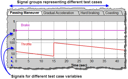
The above snapshot shows the part of Signal builder with different groups of signals from an automotive demo (type sf_car in your MATLAB installation to open this demo). In this case the different groups have the brake and throttle signals for different driving conditions. The gear shift logic modeled in Stateflow is fed with these test cases to see if the gear shifting is as expected.
Creating and importing test case signals
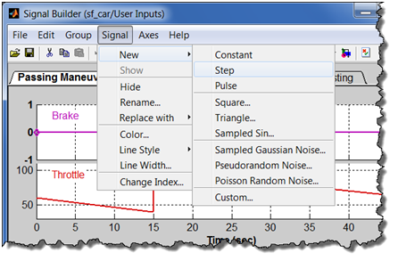
The easiest way to create a test case signal is to use one of the several built-in signals as the starting point and then modify it further to exactly represent the test conditions. Note that using the Custom option you can also use a MATLAB variable to bring in signal data into the Signal Builder.
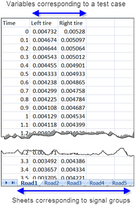
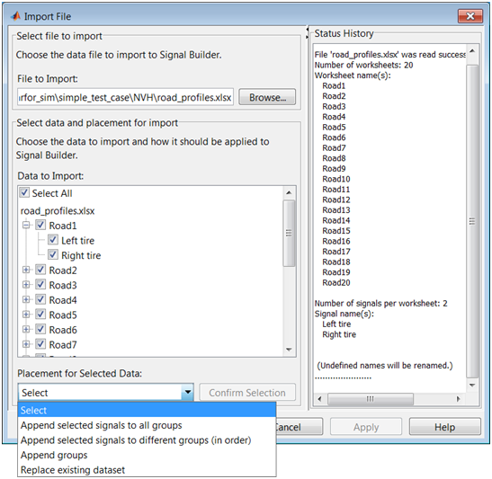
Starting in R2010b you can directly import test cases from Excel or MAT files. Here I have some road profile data in an Excel sheet. To create multiple signal groups in the signal builder, the different test cases need to be in separate sheets as shown in the figure below.
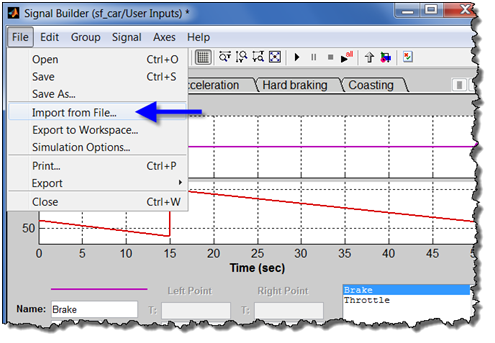
To import this test case data into Signal Builder, select the “Import from File” option in the File menu.
In the Import dialog, select the signals and groups to be imported and how they will be placed in the Signal Builder interface. The Status History pane of the Import Dialog should help you configuring the import properly.
Now it's your turn!
How do you manage test cases in Simulink? Leave a comment here and tell me about it.
- Category:
- Model-Based Design,
- Signals


Comments
To leave a comment, please click here to sign in to your MathWorks Account or create a new one.