
Modeling Mechanical Systems: The Double Pendulum
Do you ever have to model mechanical systems? Mechanical systems consist of bodies, joints, and force elements like springs. In this post, I will show you how to model a double pendulum with base Simulink and using SimMechanics.
Update - 9/14/2015: This blog post uses SimMechanics First Generation. Examples implementing double-pendulum using SimMechanics Second Generation can be found here.
Pendulum: Equations of Motion
Most of the models I work with are representations of data flow and algorithms. If you want a model of a mechanical system, you need the equations of motion so you can build the system from base Simulink blocks. Of course, if you don’t know the equations for a pendulum, you must derive them.

If you start with that equation, and follow the process described in a previous post about how to draw ODEs, the model of a pendulum looks like this:

This model is a graphical representation of mathematical operations and algorithm elements. Simulink solves the differential equation by evaluating the individual blocks according to the sorted order to compute derivatives for the states. The solver uses numeric integration to compute the evolution of states through time.
Drawing the Mechanical System
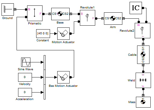
SimMechanics provides an alternative to deriving equations and implementing them with base blocks. Instead of representing a mathematical model of the system, we develop a representation that describes the key components of the mechanical system. The base units in SimMechanics are physical elements instead of algorithm elements. To build a SimMechanics model, you must break down the mechanical system into the building blocks that describe it. When you think about the pendulum, it a body connected to a joint, and that joint is connected to some kind of base, we will call that the ground.

The base elements in the SimMechanics library have special names that precisely describe what they are. I didn’t know this until I started using SimMechanics, but the joint in my pendulum example is called a Revolute. To build this system, we grab the appropriate blocks and connect them together (kind of like playing with legos!). The ports on the SimMechanics blocks are connector ports, and the “signals” running between them are connector lines. These lines do not represent data flow, they represent mechanical connections between elements.

These special connection lines and connection ports cannot connect directly to Simulink signals and ports. Sensors allow you to tap into a mechanical component and measure its physical properties. In my pendulum model above, I have measured the angular position (ap) and angular velocity (av) of the revolute joint.
When you simulate a SimMechanics model, the process is a little different from regular Simulink data flow. At initialization, SimMechanics analyzes the mechanical system to determine the topology and geometry of the machine. At run-time, the external forces and torques are applied to the machine, integrated, and the machine state is updates. Because the model may contain constraints, the solver checks for the agreement of all the elements of the machine within acceptable tolerances. The “blocks” that make up the machine do not run one at a time in the simulation loop like regular Simulink blocks.
The Double Pendulum: Equations of Motion
Let’s compare the modeling process for a double pendulum between base Simulink blocks and using SimMechanics. I don’t know the equations of motion for a double pendulum off the top of my head, so we can derive them.

Aside from the cramp in my hand from attempting to make my writing legible, the implementation in base blocks is a little more difficult. There are physical connections between the state variables, and if implemented as written above, you get algebraic loops.

Drawing the Double Pendulum
To make a double pendulum using SimMechanics I just duplicate the first joint and body to make a second arm connected at the end of the first.

In literally seconds, I converted the pendulum model to a double pendulum model.

Now It’s Your Turn
How would you model a three-jointed pendulum? How about N-joints? Leave a comment here and let us know if you would derive the equations, or reach for SimMechanics.
- Category:
- Modeling,
- ODEs,
- Physical Modeling,
- Simulation


Comments
To leave a comment, please click here to sign in to your MathWorks Account or create a new one.