
The Easiest Way to Import Signals Into Your Model
A benefit of Model-Based Design is using the same model to accomplish several tasks: tuning, testing, debugging, combining component models into larger system models, etc. Ideally, you should not have to modify your model to accomplish all of these tasks.
In Simulink, there are many techniques for importing signals into a model. With that in mind, the root-level Input Ports are the most convenient approach for importing data and maintaining model flexibility. The root-level input port allows you to test your model with signals from the workspace and use your model as referenced model in a larger context without any modification.
Importing Data to Root-Level Input Ports
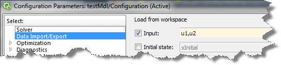
When you have Inport blocks at the root-level of your model, you can go to the Data Import/Export section of the model Configuration and specify which data should be used.
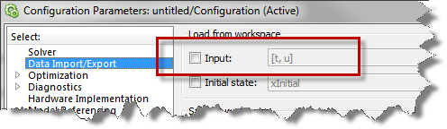
The challenge here is that the Input: field accepts so many different syntaxes that it is difficult to remember what to type here. Root inputs have been part of Simulink since version 1.0. As Simulink evolved, the root Input Port evolved to accept all the new data types and signal specifications that were added to Simulink. To ensure backward compatibility, the Input: field remained as free text.
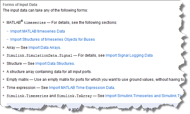
Here is a screen capture from the documentation listing the different forms of input data supported. Of course, the syntax for each of them is different.
The Root Inport Mapping dialog
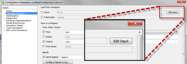
In R2012b, a new dialog was added to help filling the Input: text field. To launch it, click on the Edit Input button.
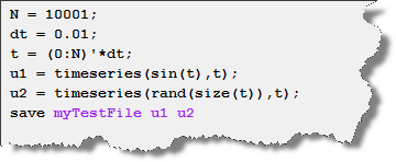
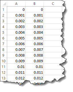
For example, let's say I have a model with two Inport blocks named u1 and u2. I can create a MAT-file containing 2 signals u1 and u2 using this example code:
I click the Edit Signal button, select the MAT-file, select the Block Name option and click the Map Signals button. The dialog will verify that the data in the MAT-file is compatible with the model and show you the result:
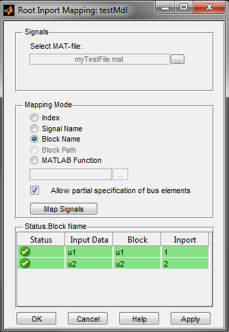
If the mapping is successful, you can click apply and the text in the Input: field will be updated:
Now it's your turn
This example is very simple, but for for more complex cases the Root Inport Mapping dialog is very useful. Did you have a chance to try it? Was it useful? Let us know by leaving a comment here.
- Category:
- Model-Based Design,
- Signals,
- What's new?


Comments
To leave a comment, please click here to sign in to your MathWorks Account or create a new one.