
Nonvirtual Bus Signals
Most Simulink users have a good idea of what a bus signal is but I have found people are not as clear about what distinguishes virtual and nonvirtual buses. We have discussed bus signals in recent posts, and we are now ready to answer blog reader Han Geerligs request for “more explanation on virtal/nonvirtual buses.”
What is a nonvirtual bus?
Here are the two types of bus signals, virtual and nonvirtual.

To make a bus nonvirtual, provide a bus object and check the “Output as nonvirtual bus” check box in the Bus Creator dialog. You can review how to make a bus object with the example provided in this previous post.

The big difference between virtual and nonvirtual buses is how Simulink treats memory allocation. A virtual bus does not allocate specific memory for the bus, whereas nonvirtual bus signals represent memory.
In a previous post, we saw that when you update your diagram (Ctrl-D), the virtual buses disappear and what remains are connections between the actual source and the destination block. The memory allocated for those signals is not contiguous. Using a nonvirtual bus specifies the creation of a structure, which resides in contiguous memory.
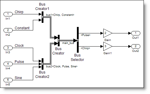
At first, this concept was foreign to me because I generally had not thought about memory allocation in Simulink. To better illustrate this concept I will compare two models, simplebusdemo_vir.mdl and simplebusdemo_nv.mdl. (Bus objects are in simplebusdemo_nv_busobjects.mat.)


Both use bus objects to specify the interface to the ReusableFcn subsystem, but simplebusdemo_nv has a nonvirtual bus crossing the boundary. Here is my mental picture of memory being allocated for the virtual bus example.

The first and fifth inport have type double inputs, with one and two elements respectively represented in red. The second inport has three elements of int16, represented in green. The third inport is one element of type uint32 represented by orange, and the fourth inport is one element of type single represented by blue. The bus creators and bus signals are all virtual blocks, so there is no memory associated with those blocks or their ports.
The inports for the nonvirtual bus example have the same pattern of memory allocation, but now we have to add in the memory for the nonvirtual bus. Here is the way I picture it.
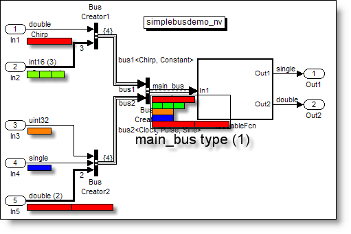
The output of the bus creator is a scalar element of main_bus type as defined by the bus object. The bus object is the definition, and the nonvirtual bus is an instance of a structure with that definition. I often see confusion between bus objects and instances defined by bus objects. They are not the same thing. The bus object is a definition of an interface. Your model may contain many instances that share that same interface definition.
Nonvirtual bus signals and efficiency
As you can see from the above picture, the nonvirtual bus has added memory to the model. In this case, that memory consists of copies of the memory defined at the inports. I have often heard the rumor that bus signals result in many unnecessary copies. This is not completely accurate. Nonvirtual bus signals can result in additional copies, but from the Simulink engine perspective, this is the specification. Another way to build this model would be to remove the five inports and replace them with a single inport, which outputs a main_bus type. Then it would look like this.

Notice, when you specify a bus object on an inport, the icon changes to show that a bus object defines that interface.
When do you need a nonvirtual bus?
The only places you need nonvirtual buses are at the boundaries in your model when you want to define the interface as a structure. Some examples of these boundaries are Stateflow charts and model reference blocks. At the interface between systems, virtual buses are as a collection of individual elements, with each passing separately to the system. The nonvirtual bus forces the memory to be a contiguous structure passed into the system.
Nonvirtual buses show up in other places in models where they are not required by semantics. Most often the reason it is done is to control the signal memory allocation in the generate code.
Virtual versus nonvirtual buses
To summarize,
- Virtual buses don’t really exist in memory (the memory they represent is at the actual source)
- Virtual bus elements are not contiguous in memory
- Nonvirtual buses resides in contiguous memory
- Nonvirtual buses may incur copies which could reduce the efficiency of the system
- Virtual buses will often require less memory
I think these concepts still require further illustration by looking at the generated code. You can get a sneak peak if you want to download the models and build the code yourself, or, tune in next week when I post about bus signals in the generated code.
Now it’s your turn
Do you ever picture the memory allocated in your Simulink model? Did I describe the reason you use nonvirtual bus signals? Are there other reasons I didn’t consider? Post a comment and share your thoughts.
- Category:
- Signals


See Also
-

Bus Copies Explained!
Blogs
-
-
-

Comments
To leave a comment, please click here to sign in to your MathWorks Account or create a new one.