Seth on Simulink

August 5th, 2008

Advanced Masking Concepts

Masking does more than just put a professional interface on your algorithm.  Simulink blocksets provide elaborate graphical user interfaces (GUIs) to control the behavior of blocks.  The block dialog can dynamically enable and disable its GUI elements.  Blocks can sprout additional ports in order to accept parameters as input signals.  The algorithm can rewire itself based on the setting in the dialog.  Did you ever ask yourself, “how can I do that?”

This is the first in a series of posts that will introduce these advanced masking concepts.  I have created an example that has:

  • A block dialog that enables and disables parameters based on user settings
  • The option to add and delete ports to match dialog settings

This example builds on top of the basic concepts introduced in my recent post on masking.  That post covered how to make a mask icon, and provide a mask dialog to control the parameters used in an algorithm.

Two saturation blocks

The example I have created combines the dynamic saturation block from a recent post on libraries and the fixed saturation block in my recent post on masking.  The algorithms for these two blocks differ slightly.  The dynamic saturation block uses inports to provide the limits, and the fixed saturation uses constant blocks to provide the same signals.

Dynamic limits and fixed limits saturation systems

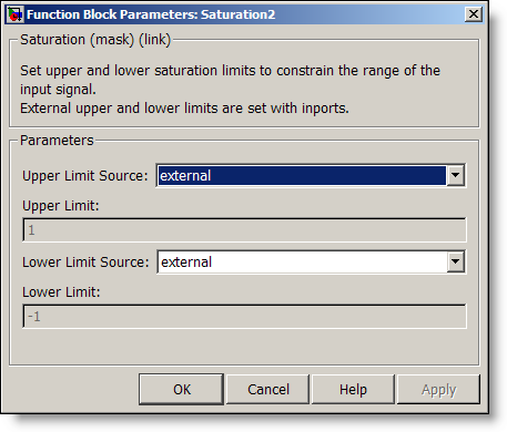
The Fixed Saturation block has a mask that sets the values of the uplim and lowlim variables in the mask workspace.

Fixed saturation limit mask dialog

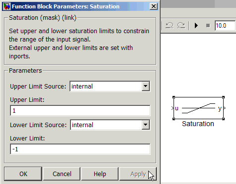
A combined saturation block interface

To combine these blocks, I present the user with a simple interface that allows them to control the source of their upper and lower saturation limits.  The value can be internal or external. 

Mask dialog for the saturation block, internal source for limits

When internal limits are used, the value comes from the Upper Limit and Lower Limit fields.  When using external limits, those fields are disabled, and inports provide the limit signals.

Mask dialog for the saturation block, external source for limits

How does this combined block work?

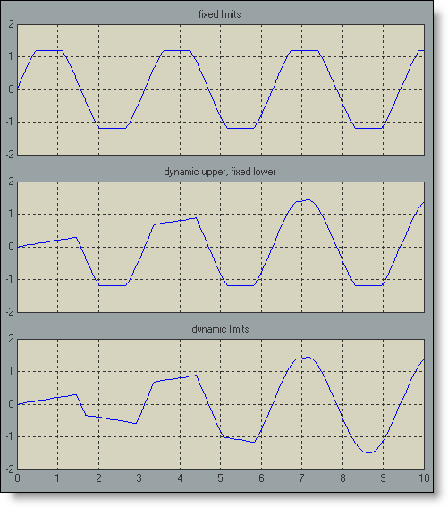
Here is a test model that exercises some of the different modes of this saturation block.  The three saturation blocks in this model are actually three instances of the same library block.

Saturation block test model

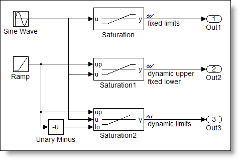
The top block uses the fixed limits.  The middle block uses an external source for the upper limit and a fixed value for the lower limit.  The bottom block uses external sources for both the upper and lower limit.

Saturatino block test model scopes

How does the same block behave in these three different ways?  To see how, you can look under the masks of these blocks and see the blocks involved in the algorithm.

Algorithms for three instances of the saturation block, fixed limits, dynamic upper and fixed lower, dynamic upper and lower

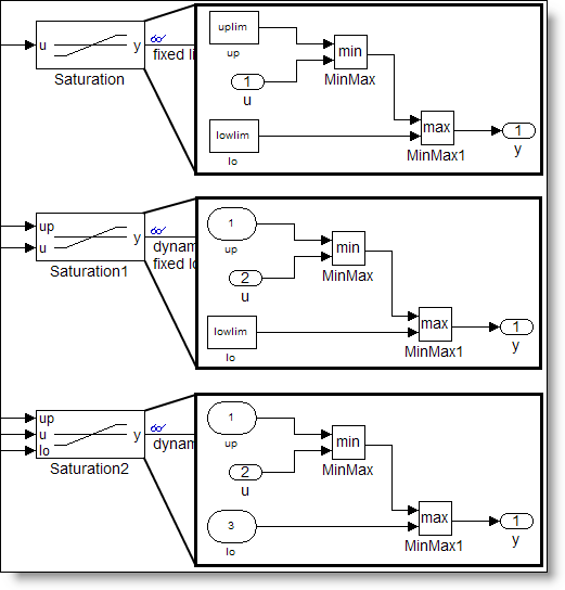
All three instances of the subsystems get their upper limit from a block named system/up, and their lower limit from a block named system/lo.  In the case where the limits are fixed, the block is a constant block.  In the case where the limit is dynamic (external source), the block is an inport.  To achieve this, the block runs some M-code that replaces the Constant block with an Inport when the source is external and replaces the Inport with a Constant block when the source is internal.

In future posts we will examine:

  • Mask dialog callbacks
  • Mask initialization and self modifiable library blocks
  • Best practices for masking

Now it’s your turn

Have you implemented masks using these concepts?  Share your experience here.

10 Responses to “Advanced Masking Concepts”

  1. Bob replied on :

    I’ve done a few more advanced blocks like this. While a bit more complex than regular blocks, I’ve found them much easier to debug than doing the equivalent in S-Functions.

    Although, I tend to hide unused parameters rather than just grey them out.

  2. Matt Rhodes replied on :

    Seth-
    Ive been a Simulink user for about 8 years now across many and varied projects in both academia and enterprise, and have always loved how much time i save using such a great tool. I’ve used custom masked blocks many times to convey concepts of the model. One thing i’ve always thought would be useful, would be to allow in and out ports on both sides of a block simultaneously in order to facilitate neater, more straightforward routing of signals. Ive managed to create blocks that allow this, but im having difficulty making the ends meet to make it completely functional. Do you know of any ways to do this easily. We are in the process of creating some very complex models, and being able to do this would be a difference of night and day for understanding the simulation diagrams. Thanks,
    -Matt

  3. Matt Rhodes replied on :

    Seth-

    Nevermind, I’ve figured this out and it works fine. Using this technique, however, is incompatible with the mask drawing command “port_label()” The workaround is to let it use its own labeling, and make the icon transparent… if making any kind of icon for the block, you pretty much have to use normalized or pixels as well or your port labels will probably get covered up.

    -Matt

  4. Seth replied on :

    @Matt Rhodes - Thanks for the comments Matt. I’m interested in the solution you used. The capability to put inports and outports on both sides of the block is a long requested feature.

  5. Ryan replied on :

    @Matt

    Interestingly, just the other day I was wondering if it was possible to create inports or outports on the top and bottom sides of the blocks.
    I was creating data flow diagrams in Visio and then I thought…”Hey…If I could do this in Simulink, wouldn’t it be easy to create a concept diagram into a working model??”

    It would be interesting to see if your solution could do this as well.

    One feature that I would also like to see is to be able to create coloured signals just the same way as subsystems or ports. Currently, the signals inherit the colour from the subsystem they originate from. I don’t know if there’s a way to manipulate this though.
    It would be very easy to trace a particular signal within a complex model if it had a colour code. Any thoughts ?

  6. Ryan replied on :

    @Matt

    Just to add in - To solve the problem of neater routing of signals, one way to do it is to use goto and from block for messey connections and use the same background colour for both the blocks.
    The use of goto and from is usually not adviced. However, if the model is only for simulation, I guess it shouldnt be a problem.

  7. Seth replied on :

    @Ryan - thanks for adding to the discussion. I am not one of those people who universally decry the use of GoTo and From blocks. I think they serve a very important purpose when cleaning up the look of a diagram. Instances where GoTo and From cause problems are usually when there is no consistency in how they are applied. My personal preference is to see the application of modeling standards to the use of GoTo/From. For example, if all GoTo and From use will be local to a system, and never global, I think this can go a long way to cleaning up the diagram. I also like your idea of using colors to match up the pairs of blocks, or to group them in some way.

    Regarding your request to provide signal specific coloring, have you ever tried right click -> Highlight to Source/Destination? I find this very helpful when debugging the model. In a very large model you must be patient using this feature as the time to recolor the model is proportional to the number of blocks and lines in it. When you are done tracing, right click -> Remove Highlighting.

  8. Ryan replied on :

    @Seth

    I do share a similar point of view on the use of goto and from blocks.

    On the signal colouring, Highlight to Source/Destination is good to analyze one signal at a time. I’m trying to think of a way to classify signals based on a similar property.

    A simple example would be if I had 3 Sensors. Sensor 1 and 2 operate on 5Volts and Sensor 3 operates on 3.3 Volts .The idea is to have the signals Sensor1, Sensor2 say coloured in red and Sensor3 perhaps in green.

    I was actually expecting to see a Background (Foreground…can’t really have both for a signal :) ) colour option when I right clicked on the signal. Too bad there wasn’t one !

    I tried opening the model as a text file to see if there were properties I could manipulate. I could do this if I had just an unconnected signal - not really useful.
    But I think the way Simulink is designed it inherits the subsystem colour the signal originates from. Wonder if there’s a work around for this

  9. Seth replied on :

    @Ryan - Thanks for the clear use case! This is very helpful in explaining your request to our development team, which is exactly what I have done with it. I can’t suggest a coloring based workaround for this. I have seen people embed information in the signal label, for example: .

  10. Radu replied on :

    Is it possible to create panes in a mask? For example the “Product” block from the “Commonly used Blocks” has to panes “Main” and “Signal Attributes”. I can not find documentation on this topic.
    Thank you in advanced!

Leave a Reply

Wrap code fragments inside <pre> tags, like this:

<pre class="code">
a = magic(3);
sum(a)
</pre>

If you have a "<" character in your code, either follow it with a space or replace it with "&lt;" (including the semicolon).


Seth Popinchalk is an Application Engineer for The MathWorks. He writes here about Simulink and other MathWorks tools used in Model-Based Design.
  • Mohamamd: Hi Suth, I try to simulate a load tap-changing transformer in simulink but its control part has to be...
  • Han Geerligs: Hello Guy, thanks for the clarificaton and link. However in the documentation I am missing the...
  • Guy: @Han, you probably already know, but I think it is good to share with everyone. To zoom in use the key...
  • Han Geerligs: Hi Seth, Once again I’d like to point out that my biggest accelerator is using mouse and keyboard...
  • XaL: Hi, thanks for the tips. As someone wrote in http://blogs.mathwor ks.com/seth/2009/03/ 13/new-%C2%A0rele...
  • Uba osy: Hi, in the introductory example for fuzzy logic toolbox it was noted that using non fuzzy means, you could...
  • Prashant: How can I have same example but instead AC(1 to 10V 50 or 60Hz) and DC(0.5 to 10 V) then adding AC+DC but...
  • adrian chavarro: Great tool, for educational and sicentific, simulation. I would like to know where can i place a...
  • Ashish Sadanandan: @wei, I was talking about the case where the compiler would perform the ‘model_Xdim...
  • wei: @Ashish, I agree with your observation on compiler optimization but fail to see why Han’s code would be...

These postings are the author's and don't necessarily represent the opinions of The MathWorks.