Seth on Simulink

July 25th, 2009

Better Bus Modeling (How to remove Bus/Mux confusion)

Earlier this week, Guy and I were discussing the sometimes-strange behavior of mux and bus signals.  Sometimes people find a Mux block in their model that appears to output a bus signal.  In this post, I will explain the underlying cause of this behavior and give you a short Simulink history lesson.

Don’t let your eyes deceive you!

Most people have the correct mental model of the Mux block as a vector creator.  When you see a Mux block, the expectation is it outputs a wide signal (a vector).  Here is a very simple model that does not behave this way.

A Mux block outputing a bus signal.

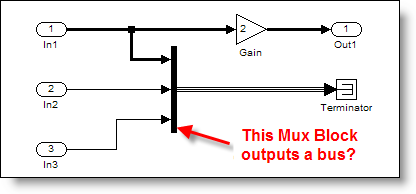
This is actually a misleading.  Mux blocks are virtual, so they don’t actually do anything during the simulation.  Virtual Bus signals are similar to Mux blocks.  The Terminator is also virtual (it doesn’t update, compute outputs, etc.)  When you consider those observations, all that is left are the ports and the Gain block.

Sometimes a Mux block can output a bus signal.  Huh?  But, I thought the Mux block created a vector!

The Mux Used to Create Bus Signals

A long time ago, in a much earlier version of Simulink, the Bus Selector was introduced to allow users to select signals by name from a bundle of signals.  The Mux block created this “bundle” of signals.  Simulink only supported vectors (no matrices), so there was very little difference between a virtual muxed signal and a virtual bus signal.

Soon after the introduction of the Bus Selector, developers added the Bus Creator to reduce confusion about the mixed meaning of Mux blocks.  At the time, the Bus Creator still behaved much like a Mux block and actually shared code with the Mux block.  For compatibility reasons, the Mux block had to continue supporting the creation of bus signals.

Over time, Simulink semantics changed and the difference between bus signals and vectors got more significant.  In R14 Simulink (circa 2004), there were edge cases where the mixing of mux and bus caused problems.  Simulink developers wanted to migrate to a clean bus modeling behavior, but it would break legacy models that depended on the Mux block to create bus signals.  It was too dramatic a change to switch to the new and improved behavior without giving modelers a way to opt-in.  How did they do it?

The Solution: Error Checking

The Connectivity Diagnostic -> Mux blocks used to create bus signals was introduced to control this behavior.  When a Mux block creates a bus, Simulink now handles it in one of three ways.

The connectivity diagnostic, Mux blocks used to create bus signals.

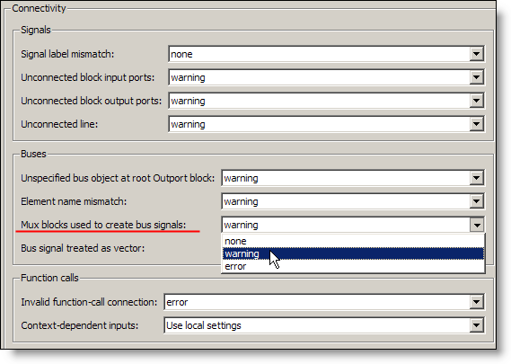
This diagnostic can be set to none, warning, or error.

none – This is the historical behavior of the Mux block, creating vector signals AND bus signals when needed.  Full backward compatibility, plus the edge cases I talked about before.

warning – This is the historical behavior of the Mux block, plus a post compile check to find Mux blocks that might be used a bus creators.  Simulink reports warnings it finds one.

error – This is the clean bus modeling behavior the developers implemented. If a Mux block is used to create a signal that is treated like a bus, an error stops the update diagram process.

Because this diagnostic asserts that it is an error to use a Mux block as a bus creator, Simulink assumes that only Bus Creators make bus signals.  This assumption resolved the edge cases and made the clean bus modeling behavior possible.  Because this is a diagnostic and the default is warning, legacy models still worked when people upgraded.  Some issues were actually resolved by changing the diagnostic to error.

How to Fix the Warning/Errror

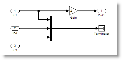
The warning and error messages provide some direction on how to resolve the problem.  There are even commands you can call to help fix your model.  This is an example of a model that produces a warning about mixing mux and bus.

A model that produces warnings about Mux blocks used as bus creators. 

Warning: The block diagram 'muxORbusWarning' improperly uses 1 Mux blocks as Bus Creators. This can lead to modeling errors (see the Mux block documentation for more information). To avoid such errors, replace the Mux blocks with Bus creator blocks and enable strict bus modeling (see slreplace_mux command). To enable strict bus modeling, set the 'Mux blocks used to create bus signals' option to 'error' in the Connectivity pane of the Diagnostics page in the Configuration Parameters Dialog.

Don't stop there!

For similar reasons you should also set Bus signal treated as vector to error.

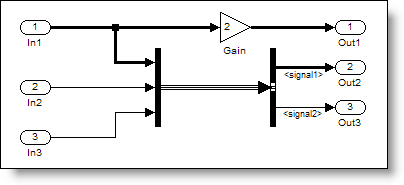
Fixing the original model

When the original model uses strict bus mode, the signal draws as a vector signal instead of a bus.

Mux blocks only output bux signals in strict bus mode.

Now it’s your turn

The take away from this post is that you should set these diagnostics to error to get the BEST mux/bus behavior.  Do you model in strict bus mode?  Tell me about it and leave a comment here.

5 Responses to “Better Bus Modeling (How to remove Bus/Mux confusion)”

  1. Angelo replied on :

    Hi Seth,

    I’m fighting with a problem involving what you described above and maybe you can suggest me some solution.
    In the attempt of assign names by command to signals entering in a block (only by accident a bus creator) I’m not able to distinguish between 2 kind of signals. For example soppose you have these signals:
    - a 3{3} signal created by a mux as you explained above
    - three scalar signals (1 1 1)
    So you have 4 signals (1+3) requiring to be named whereas counting them (for example by means of the CompiledPortDimensions parameter of the Inport of the bus creator) 6 signals (3+3) are tallied up.
    Do you know any more parameter (or way) to understand that the first 3 signals are indeed just one (it correspond only one name to them)?

    Thanks.

    angelo

  2. Guy replied on :

    @Angelo, The situation you describe seems exactly the kind of situation where the “Mux blocks used to create bus signals” diagnostic should be set to error. This should change the dimension “3{3}” to “3″. If it does not I would be very interested to get a model and reproduce. If setting this diagnostic to error is not possible for you because of other reasons, probably the Vector Concatenate block could help. This block generates a contiguous output signal.

  3. Angelo replied on :

    @Guy: Unfortunately, as you said, I can’t switch on “error” the “Mux blocks used to create bus signals” diagnostic so I’m looking for different solutions. I have found that the Mathworks ‘busCreatorddg’ function, called with a double click on bus creator, gathers all the entering signal’s structure in the ‘UserData’ field, exactly as I need. What I don’t understand is how can I call this function by command (or better by callback considering I created one for other reasons) and more in detail which arguments (’source’ and ‘block’) should I have to pass for run the function and extract the “precious” data. For the ‘block’ argument it should be the Bus Creator block (Name? Handle?) but what about ’source’?

    Do you have any clue about that?

    PS I’m trying to avoid add simulink blocks but extracting these data by command, this is why didn’t considerate the Vector Concatenate block.

    Thank you.

    angelo

  4. Guy replied on :

    @Angelo: The function “busCreatorddg” is an undocumented internal function. I recommend not using this function. It can change without advice in a future release of MATLAB. If you use it you will face problem when upgrading.

    As I mentioned previously, I would like to better understand the issue. I am not sure what you mean by “to understand that the first 3 signals are indeed just one”. When looking at a bus creator block configured as you mention, It is possible to obtain the handle to the 4 input ports of the bus creator (using get_param(gcb,’PortHandles’)) and obtain their dimension from the CompiledPortDimensions property. In that case the first signal (the one created by a mux) has a dimension of 3 and the other ports a dimension of 1.

    Maybe you could send me example model and script by email so that I could better understand what you are looking for and propose a more appropriate solution.

    Finally, I apologize for not being clear, but the Vector Concatenate block would not add blocks to your model, it would replace the mux block.

    Guy

  5. Renish replied on :

    clc;
    clear all;
    % To Open a new model file the Existing Model
    % new_system(’Chaining_Diagram’,'Model’)

    % To Open the Existing Model
    open_system(’Chaining_Diagram’)
    Pos = [115, 88, 155, 122];
    for i = 1:3
    % To add a block to the model
    h = add_block(’simulink/Ports & Subsystems/Subsystem’, ‘Chaining_Diagram/Subsystem’, ‘MakeNameUnique’, ‘on’);
    if i == 1
    add_block(’simulink/Sources/In1′,’Chaining_Diagram/Subsystem/In1′, ‘MakeNameUnique’, ‘on’);
    add_block(’simulink/Sinks/Out1′, ‘Chaining_Diagram/Subsystem/In1′, ‘MakeNameUnique’, ‘on’);
    else
    path = strcat(’Chaining_Diagram/Subsystem’,num2str(i-1),’/In1′);
    add_block(’simulink/Sources/In1′, path, ‘MakeNameUnique’, ‘on’);
    add_block(’simulink/Sinks/Out1′, path, ‘MakeNameUnique’, ‘on’);
    end
    % To set the Dimension of the block
    set_param(h, ‘Position’, Pos)
    set_param(h, ‘ShowPortLabels’,'off’)
    BlkName = strcat(’disp(’,num2str(i),’)');
    set_param(h, ‘MaskDisplay’,BlkName)
    set_param(h, ‘ShowName’,'off’)
    set_param(h, ‘Mask’,'on’)
    Pos = Pos + [0, 100, 0, 100];
    end
    add_line(’Chaining_Diagram’,'Subsystem/1′,’Subsystem2/2′,’autorouting’,'on’)
    add_line(’Chaining_Diagram’,'Subsystem/2′,’Subsystem1/1′,’autorouting’,'on’)
    add_line(’Chaining_Diagram’,'Subsystem1/1′,’Subsystem2/1′,’autorouting’,'on’)
    add_line(’Chaining_Diagram’,'Subsystem1/2′,’Subsystem/2′,’autorouting’,'on’)
    add_line(’Chaining_Diagram’,'Subsystem2/1′,’Subsystem/1′,’autorouting’,'on’)
    add_line(’Chaining_Diagram’,'Subsystem2/2′,’Subsystem1/2′,’autorouting’,'on’)

    % To save the open System
    save_system(’Chaining_Diagram’)

    *******************************************
    when this piece of code which i wrote is executed, connecting lines are getting overlapped. Any help to make it non Overlapping?
    Thanks in advance

Leave a Reply

Wrap code fragments inside <pre> tags, like this:

<pre class="code">
a = magic(3);
sum(a)
</pre>

If you have a "<" character in your code, either follow it with a space or replace it with "&lt;" (including the semicolon).


Seth Popinchalk is an Application Engineer for The MathWorks. He writes here about Simulink and other MathWorks tools used in Model-Based Design.
  • Mohamamd: Hi Suth, I try to simulate a load tap-changing transformer in simulink but its control part has to be...
  • Han Geerligs: Hello Guy, thanks for the clarificaton and link. However in the documentation I am missing the...
  • Guy: @Han, you probably already know, but I think it is good to share with everyone. To zoom in use the key...
  • Han Geerligs: Hi Seth, Once again I’d like to point out that my biggest accelerator is using mouse and keyboard...
  • XaL: Hi, thanks for the tips. As someone wrote in http://blogs.mathwor ks.com/seth/2009/03/ 13/new-%C2%A0rele...
  • Uba osy: Hi, in the introductory example for fuzzy logic toolbox it was noted that using non fuzzy means, you could...
  • Prashant: How can I have same example but instead AC(1 to 10V 50 or 60Hz) and DC(0.5 to 10 V) then adding AC+DC but...
  • adrian chavarro: Great tool, for educational and sicentific, simulation. I would like to know where can i place a...
  • Ashish Sadanandan: @wei, I was talking about the case where the compiler would perform the ‘model_Xdim...
  • wei: @Ashish, I agree with your observation on compiler optimization but fail to see why Han’s code would be...

These postings are the author's and don't necessarily represent the opinions of The MathWorks.