
From SolidWorks to SimMechanics
This week we see how to export a CAD assembly from SolidWorks to SimMechanics. Once a mechanism is translated into a SimMechanics model, we can interface it with Simulink to perform a wide range of analysis or design tasks not available in most CAD software.
The SolidWorks Assembly
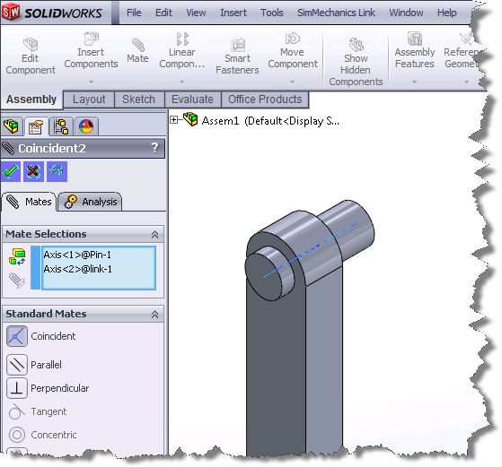
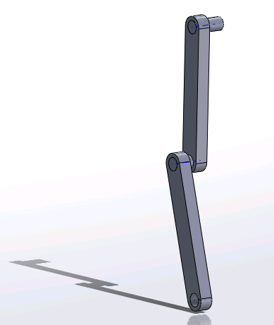
Let's start by creating an assembly of a double pendulum in SolidWorks. It consists of 2 identical links and 2 identical pins. These components are assembled by defining mates between them. For example to create a revolute joint between two parts in SolidWorks, we can constrain their axes and make them coincident:
I recommend looking at the Mates and Joints documentation page for more details on how SolidWorks mates are translated into SimMechanics Joints. For our example, here is how the final assembly looks:
Exporting the SolidWorks assembly to SimMechanics
This process requires the use of SimMechanics Link. Once SimMechanics Link is downloaded successfully, you need to Install and Register it with SolidWorks.
*Note: SimMechanics Link can also be used to interface with PTC Creo and the Autodesk Inventor.
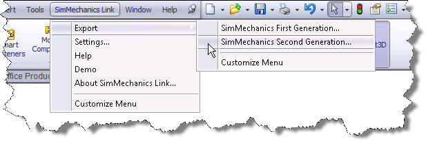
After registering SimMechanics Link, a new menu is available in SolidWorks. We can now export the assembly:
This generates an XML file for the assembly, well as STL files for the geometry. The XML file contains assembly structure and part parameters required to generate an equivalent SimMechanics model, such as reference frames, mass and inertia, color, and location of part STL files.
Create SimMechanics model
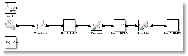
Once the XML file is exported from SolidWorks, we can import it in Simulink using smimport:
smimport('DoublePendulum.xml')
and we have a model:
Do what you came here for!
At this point, you can combine any feature available in Simulink with your mechanism. For example, we can design a controller for the base joint using the automated PID Tuning capability of Simulink Control Design
I modify the base joint to measure its position and apply a torque, and connect the PID block:
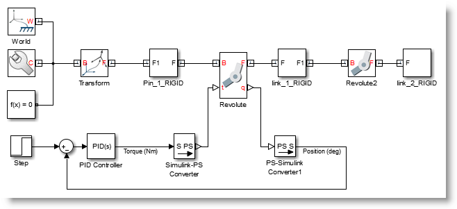
After going through the auto tuning procedure, we can see the resulting motion:
What if you’re not using SolidWorks?
As mentionned previously, SimMechanics Link can also be used to interface with PTC Creo and Autodesk Inventor. If you are designing mechanical systems using a different CAD tool, I recommend looking at the MATLAB Central submission CAD to MATLAB to SimMechanics by my colleague Steve Miller. Using the technique in this submission it might be possible to write your own adapter to import assemblies from other CAD software without too much work.
Now it's your turn
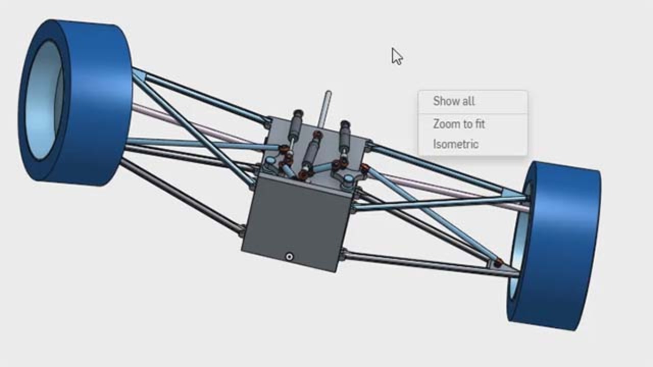
Here is one more animation from the Stewart Platform example, just to highlight that pretty complex assemblies can be imported.
Are you already importing CAD assemblies to SimMechanics? If yes, let us know what kind of analysis or design task you do with the assembly once in Simulink by leaving a comment here.
- Category:
- Physical Modeling


Comments
To leave a comment, please click here to sign in to your MathWorks Account or create a new one.